232
Chapter 7 Plug-in Modules
44470A 10-Channel MUX Module
7
Creating attenuators An attenuator is composed of two resistors that act
as a voltage divider. A typical attenuator circuit is also shown below.
To select the attenuator components, use the following equation:
One typical use for the shunt component is to convert the output of 4 to
20 mA transducers to a voltage that can be measured using a DMM.
A 50 Ω, ±1%, 0.5 watt resistor can be installed in the R2 (shunt) location
and the resultant voltage drop (transducer current through the resistor)
measured. The 50 Ω resistor converts the 4 - 20 mA current to an 0.2 - 1
volt signal. No series element (R1) is needed.
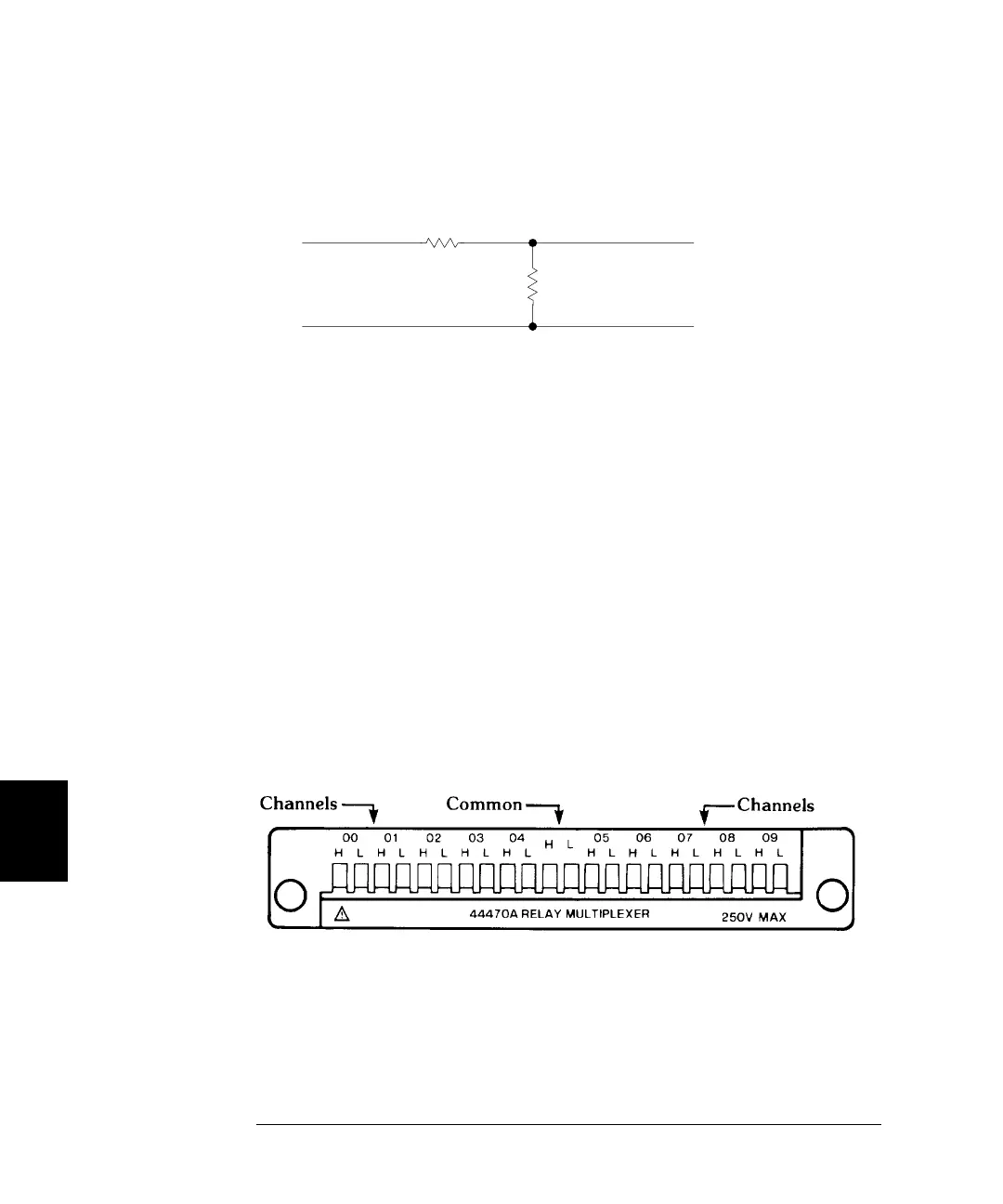
44470A Wiring Information
Use the Agilent 44480A Terminal Block to make connections to the
44470A. One 44480A is supplied with the module.
The terminal block includes a screw terminal that connects external
wiring to the 44470A. The screw terminal is shown below. Additional
information about the terminal block is given on page 285.
Vout = Vin * (R2/(R1 + R2)
R2
(series element)
SIGNAL
INPUT
Vin
SIGNAL
OUTPUT
Vout
R1
(shunt element)
()⁄×
 Loading...