246
Chapter 7 Plug-in Modules
44473A 4 x 4 2-Wire Matrix Switch Module
7
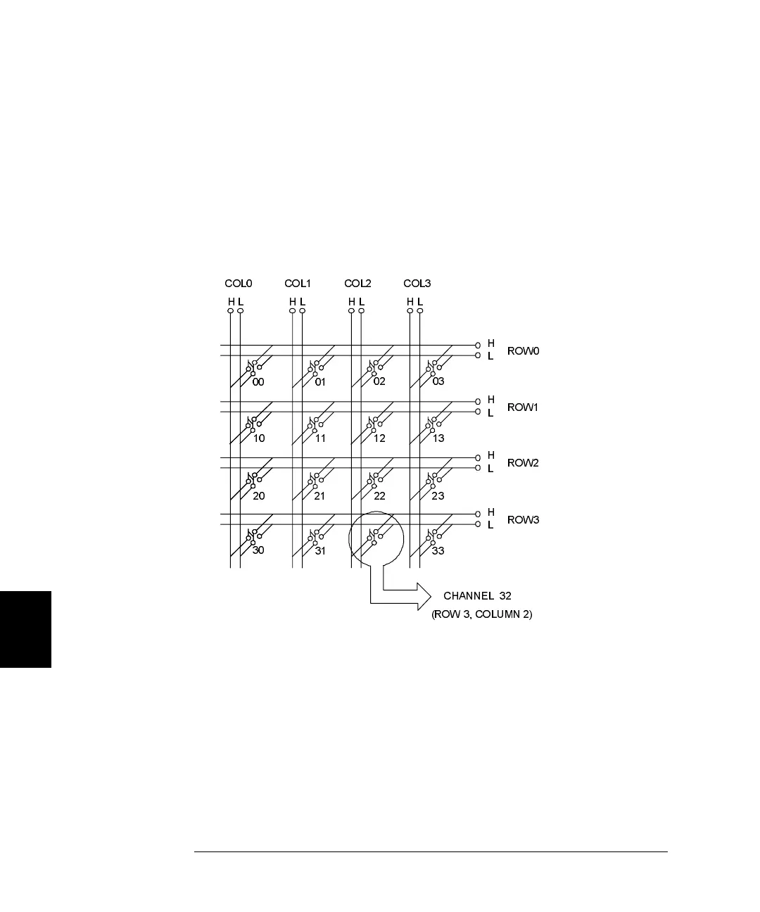
44473A Simplified Schematic
A simplified schematic is shown below. The 44473A consists of 16 2-wire
relays (nodes/crosspoints) organized in a 4-row by 4-column matrix.
Channels in this matrix module are numbered in the Row-Column
format. For example, channel 32 represents the crosspoint connection
between row 3 and column 2; while the channel 23 represents the
crosspoint connection between row 2 and column 3, and so on.
ROW0
COL0
ROW1
COL1
ROW2
COL2
ROW3
COL3
HL
H
L
CHANNEL 32
(ROW 3, COLUMN 2)
HLHL HL
H
L
H
L
H
L
00 01
02 03
10
11 12 13
20
21
22 23
30
31 33
 Loading...