249
Chapter 7 Plug-in Modules
44474A 16-Bit Digital I/O Module
4
7
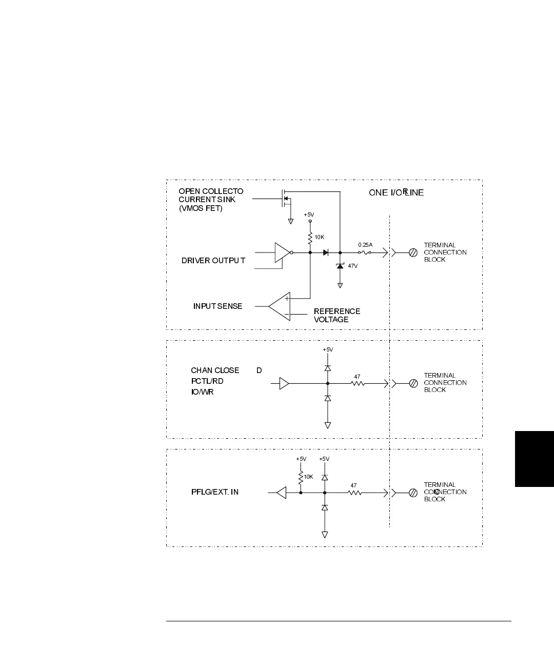
44474A Simplified Schematic
A simplified schematic is shown below. Note that all 16 I/O lines and 4
control lines share a common Lo connection. The 16 bits (I/O lines) are
numbered as bits 0 through 15 when the module is addressed
individually. The bits 0-7 refer to the bits 0-7 of the LO BYTE, and the
bits 8-15 refer to the bits 0-7 of the HI BYTE.
CHAN CLOSE D
PCTL/RD
IO/WR
TERMINAL
CONNECTION
BLOCK
PFLG/EXT. IN C
TERMINAL
CONNECTION
BLOCK
+5V
47
+5V
47
+5V
10K
+5V
47V
OPEN COLLECTO R
CURRENT SINK
(VMOS FET)
DRIVER OUTPU T
INPUT SENSE
REFERENCE
VOLTAGE
ONE I/O LINE
0.25A
TERMINAL
CONNECTION
BLOCK
10K
 Loading...