253
Chapter 7 Plug-in Modules
44475A Breadboard Module
4
7
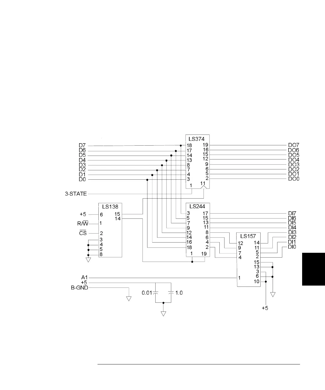
44475A Simplified Schematic
A simplified schematic of the breadboard interface is shown below. The
44475A is divided into two areas. They are:
1. Breadboarding Grid consisting of holes on 0.10 inch centers. There is
0.030 inch spacing between foil pads. Bus traces for power supply and
ground, and provisions for the screw terminal block edge connector
are provided.
2. Built-in design for providing an 8-bit digital input port and an 8-bit
digital output port.
3-STATE
D0
D1
D2
D3
D4
D5
D6
D7
+5
R/W
CS
A1
+5
B-GND
0.01
1.0
+5
DI0
DI1
DI2
DI3
DI4
DI5
DI6
DI7
DO0
DO1
DO2
DO3
DO4
DO5
DO6
DO7
LS374
LS138
LS244
LS157
6
1
2
3
4
5
8
15
14
3
5
7
9
12
14
16
18
1
19
2
4
6
8
11
13
15
17
18
17
14
13
8
7
4
3
1
11
19
16
15
12
9
6
5
2
12
9
4
1
14
11
5
2
15
13
3
6
10
7
 Loading...