EasyManuals Logo

Agilent Technologies Agilent 3499A User Manual

Agilent Technologies Agilent 3499A
357 pages
To Next Page IconTo Next Page
To Previous Page IconTo Previous Page
Page #264 background imageLoading...
Page #264 background image
264
Chapter 7 Plug-in Modules
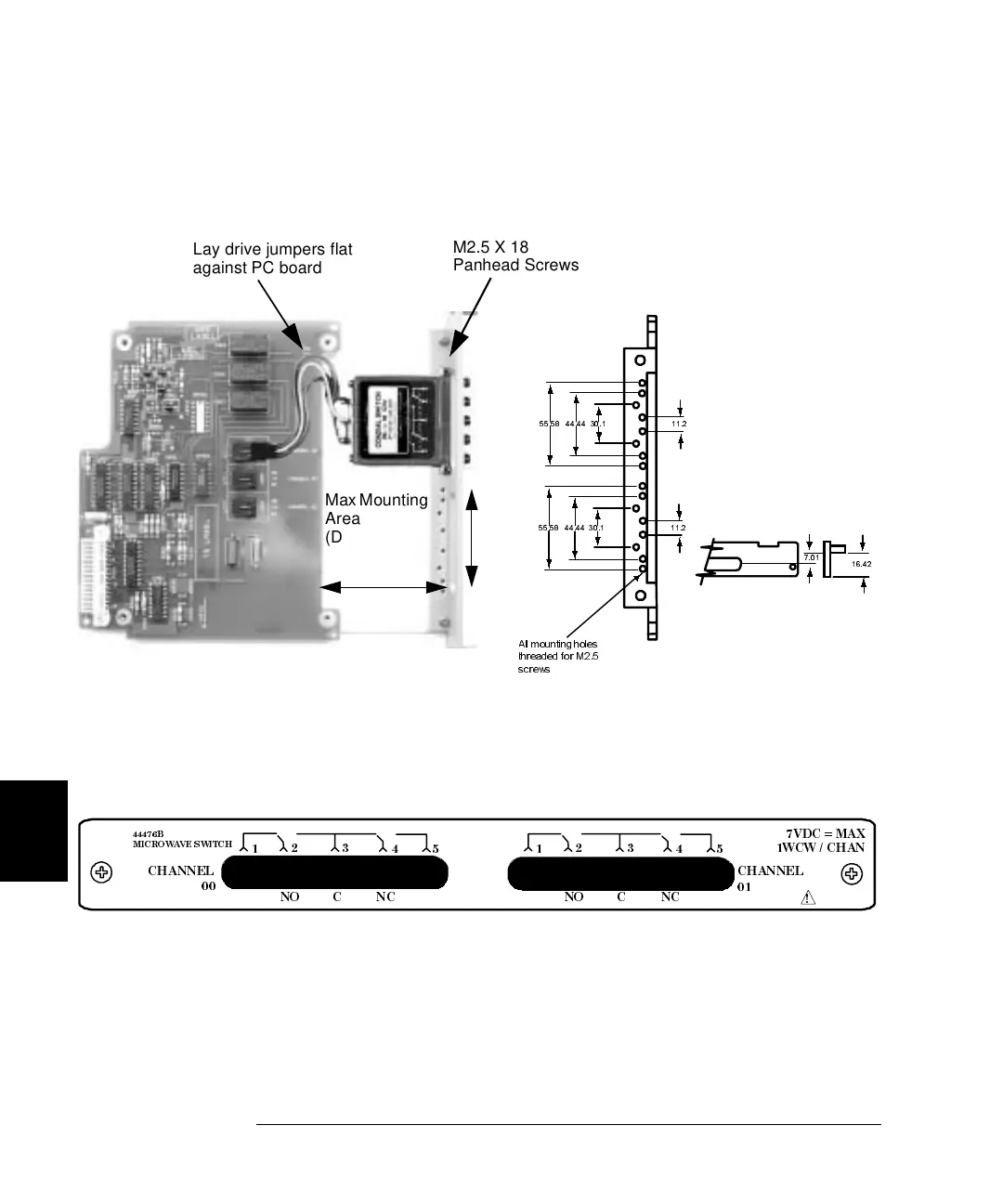
44476B Microwave Switch Module
7
The figure below shows an Agilent 8764B 5-port switch mounted on the
44476B.
44476B Wiring Information
The user-provided switches use 50 SMA connectors (except the Agilent
8762F which uses 75 SMA connectors).
A
ll mounting holes
t
hreaded for M2.5
screws
55.58 44.44 30.1 11.2
55.58 44.44 30.1
11.2
7.01
16.42
M2.5 X 18
Panhead Screws
Lay drive jumpers flat
against PC board
Max Mounting
Area
(D=14.1 mm)
62 mm
66 mm
44476B
MICROWAVE SWITCH
CHANNEL
00
1
23
45 1
23
45
NO
CNC
NO
CNC
CHANNEL
01
7VDC = MAX
1WCW / CHAN
!

Table of Contents

Questions and Answers:

Question and Answer IconNeed help?

Do you have a question about the Agilent Technologies Agilent 3499A and is the answer not in the manual?

Agilent Technologies Agilent 3499A Specifications

General IconGeneral
BrandAgilent Technologies
ModelAgilent 3499A
CategoryControl Systems
LanguageEnglish