7
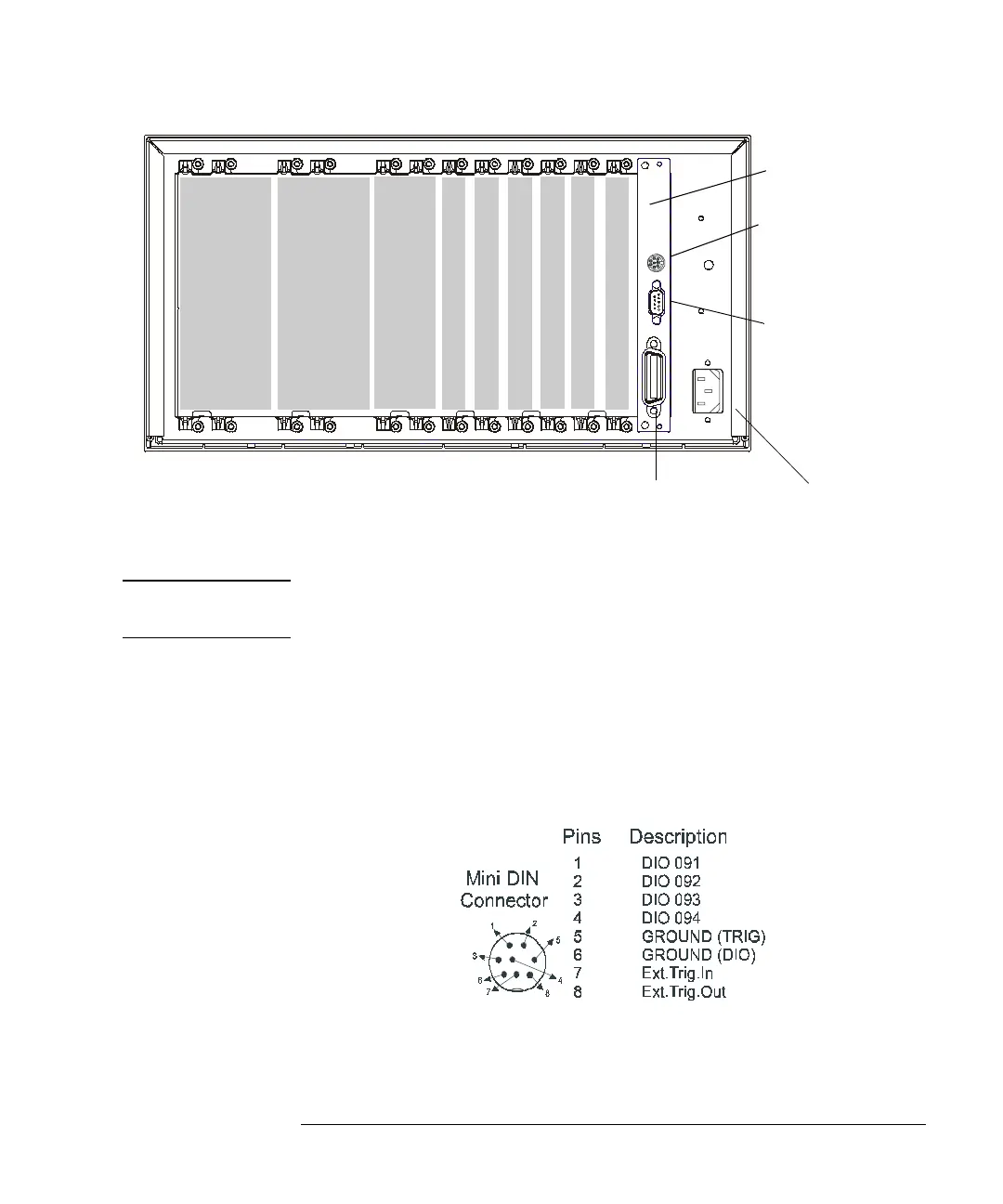
The figure below shows the Agilent 3499C rear panel.
Option FP1 (1-slot) and FP2 (2-slot) filler panels can be ordered to cover
any unused slots.
WARNING For protection from electrical shock, the power cord ground must not be
defeated.
The Mini DIN Connector
The rear panel mini DIN connector is used to make connections to
external triggers and the built-in digital I/O port. An Agilent N2289A
cable (mini DIN to D9) can be ordered to assist connections to external
devices. The figure below shows the pins used in the mini DIN connector.
GPIB Connector
RS-232 Connector
Mini DIN Connector
Power Input
Slot 1
Slot 2
Slot 3
Slot 4
Slot 5
Slot 6
Slot 7
(2 slot width)
Slot 8
(3 slot width)
Slot 9
(3 slot width)
Slot 0
Control Module
 Loading...