93
Chapter 4 Features and Functions
Scanning
4
4
Using External Triggering
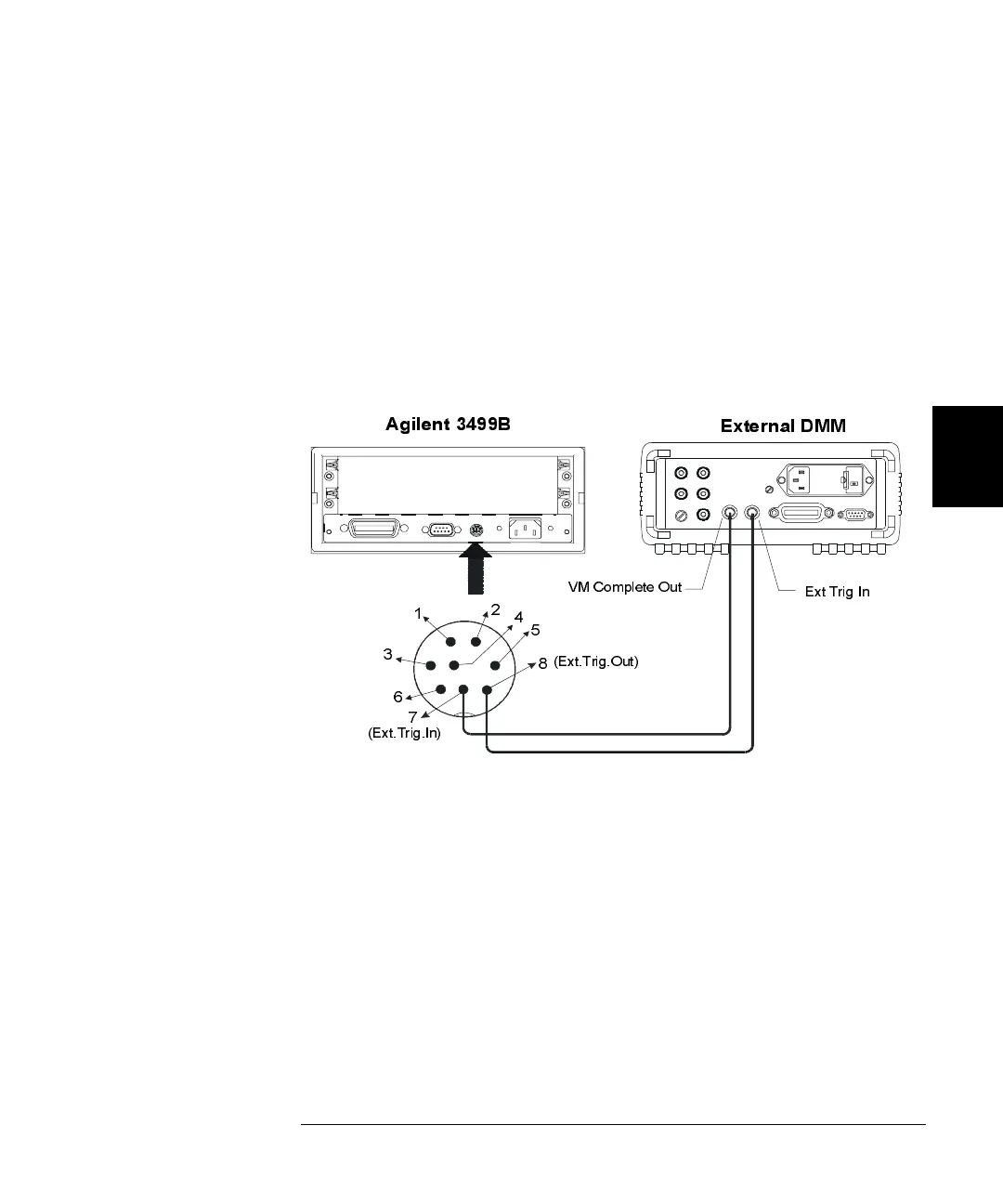
Two control lines are provided in the rear panel mini-DIN connector:
external trigger in and external trigger out. These lines can be used
individually or combined to synchronize a scan list with an external
instrument (such as a DMM). The figure below shows this connection.
The 3499A/B/C can be configured to output a trigger pulse to notify the
external instrument whenever a channel is closed. The arm or trigger
source is then configured as either EXT or MIX so that the 3499A/B/C can
receive the notification from the external instrument to advance to the
next channel in the scan list.
•
In addition to the Ext.Trig.In and Ext.Trig.Out pair provided on the
rear panel of the mainframe, the EI (external increment) and CC
(channel closed) pair on a 44474A module (see page 248) can also be
used to synchronize. Specify either Slot 0 or the slot in which a
44474A module is installed to indicate which lines are to be used.
•
Both the built-in trigger lines and the EI/CC lines on the 44474A are
TTL compatible.
•
Once enabled, the selected trigger-in line is immediately ready to
accept the trigger signal from the external instrument. Enabling or
disabling a trigger source from the front-panel sets both the trigger in
and trigger out functions. On the remote interface, the trigger out
function can be controlled independently.
2
3
5
6
8
VM Complete Out
Ext Trig In
(Ext.Trig.Out)
7
(Ext.Trig.In)
Agilent 3499B
External DMM
1
4
 Loading...