Agilent 1200 Series Autosampler Reference Manual 239
Theory of Operation 8
Sampling Unit Control
Needle arm, metering device and valve motors are driven by controlled
pulse-width modulation in the same way as the SGS L6506 (see “Transport
Unit Control” on page 238). The motors require fast speed but do not require
precise position control. Therefore, a closed loop servo system is not required.
Commutation is done in FPGA logic. The needle arm, metering device and
valve motors use SGS L6203 output drivers to deliver the higher currents
required for fast movement or high torque.
The movement sensing of the valve motor is done by two microswitches. Two
reflection light sensors are used to detect the end positions of the needle arm.
One photo sensor is required to detect the home position of the metering
device. Two hall sensors detect correct closure of the door (needle arm
movement is interrupted if the door is open). All the sensors are mounted on
one flex board. The flex board and motors are connected to the sampling unit
distribution board (SUD). The SUD board is connected to the autosampler
main board (ASM) via a flat-band cable (64 pin).
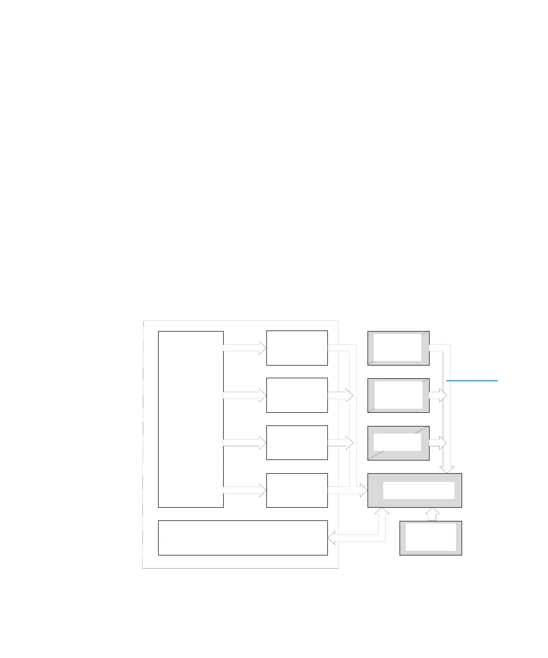
Figure 38 Sampling unit control
FPGA
Sensor Circuits
Needle
Drive
Valve Drive
4.5A/Phas
Mixing
Drive
Metering
Drive
Needle
End-Position
Metering
Home-Positi
Safety Hall
Sensors (2)
Sampling Unit
Distribution Board
Valve
End-Position
Sampler Main
Via
sampling
unit flex
board
 Loading...


