28 Agilent 1100 Series Fraction Collectors User’s Guide
1 Configuration and Operation of the Fraction Collector
Setting up a Fraction Collector Method
Peak-based If Peak-based is selected the collection of fraction is triggered by
the signal of the detector, e.g. diode array detector or mass selective detector.
The detailed trigger conditions are specified in the Peak Detectors table. The
Peak-based trigger mode overrules all settings in the Timetable below.
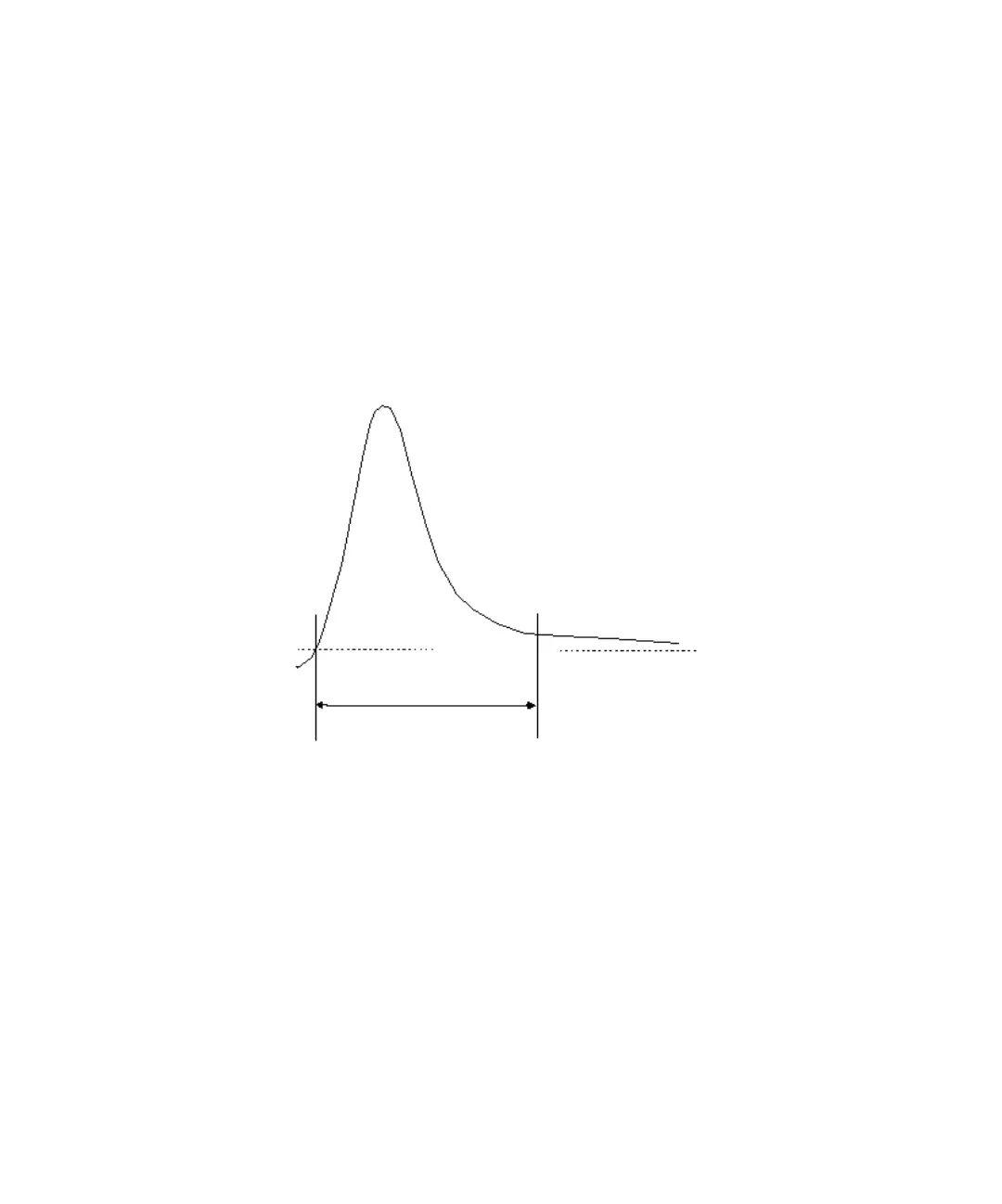
Max. Peak Duration Defines a maximum collection time in case that the signal
does not reach the condition to cut the fraction as exhibited in Figure 11. The
could be caused by tailing peaks or if the baseline is drifting during gradient
runs.
Peak Detectors
In the Peak Detectors section a list of all Peak Detectors that are connected to
the system is displayed. Agilent 1100 Series Diode Array Detectors, Multiple
Wavelength Detectors and Variable Wavelength Detectors are recognized
automatically. Other Detectors, e.g. 1100 Series Mass Selective Detectors,
Fluorescence Detectors or HP1050 Detectors, are connected through the
Universal Interface Box (UIB).
The Peak detector table contains seven columns:
Figure 11 Maximum Fraction Duration
Threshold
Max. Peak Duration
 Loading...