Agilent 1100 Series Fraction Collectors User’s Guide 61
Repairing the Fraction Collector 3
Simple Repairs
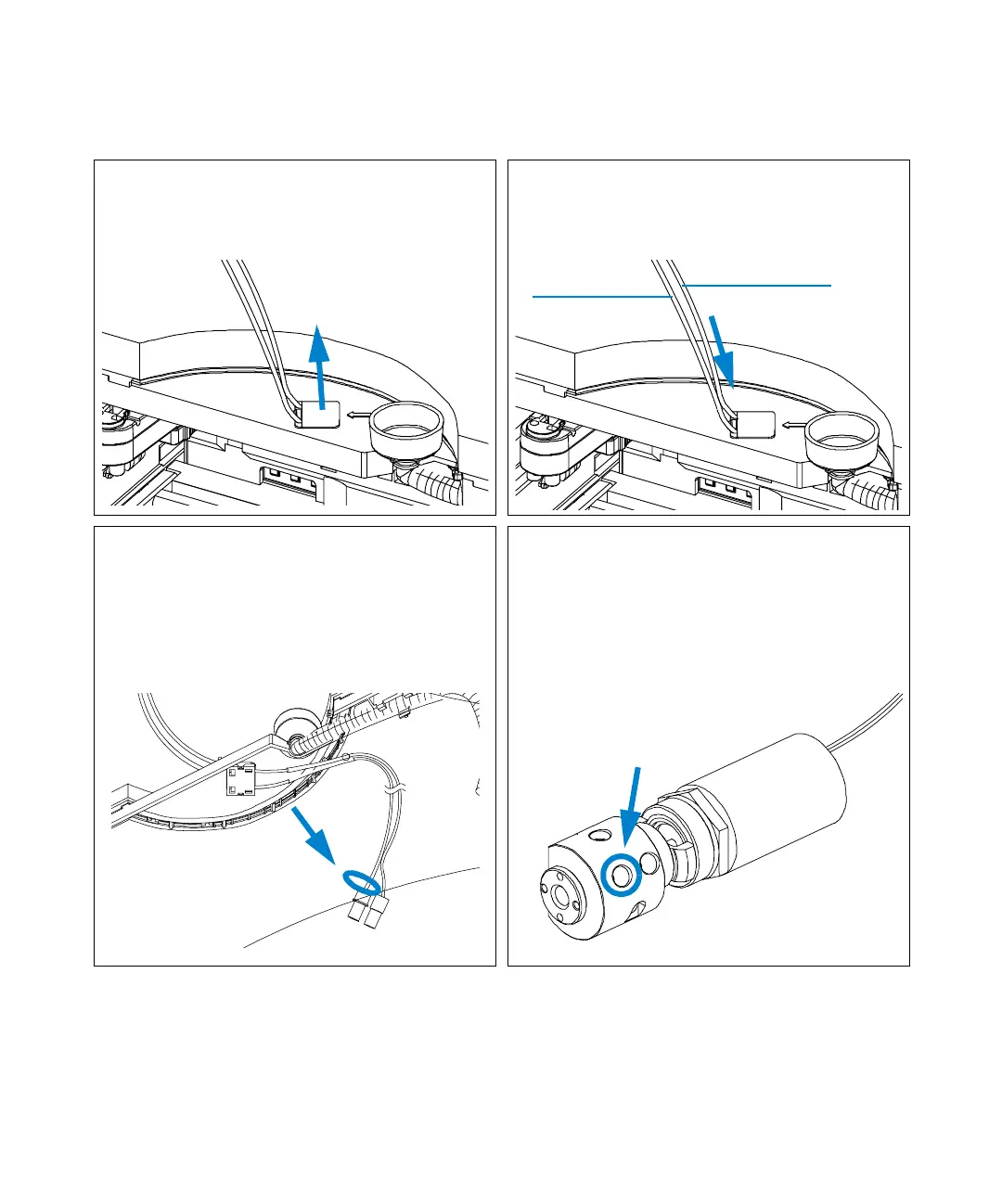
4 Install the new inlet / waste tubing assembly
into the bolt carrier as shown below. Slide in
the long ends of the tubings from bottom to
top and let the snapper click into position.
5 The rear tubing (with the label with the
arrow) must be connected to the flow cell of
the detector. The front tubing must be
inserted into the waste container.
6 Connect the finger-tight fittings of the inlet /
waste tubing assembly to the ports of the
diverter valve.
IMPORTANT: The tubings must not be bent
up- or downwards. The cables must not be
twisted.
(View from the bottom)
7 A color coded ring on one of the tubings and
the valve body indicates, which cable belongs
to which port.
IMPORTANT: It is absolutely vital to
connect these tubings as described, in
order to maximize their lifetime and
operating security.
From flow cell
To w as te

 Loading...