Agilent InfinityLab LC Series Diode Array Detectors User Manual 182
11 Identifying Cables
Remote Cables
One end of these cables provides a Agilent Technologies APG (Analytical
Products Group) remote connector to be connected to Agilent modules. The
other end depends on the instrument to be connected to.
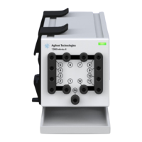
Agilent Module to Agilent 35900 A/D Converters
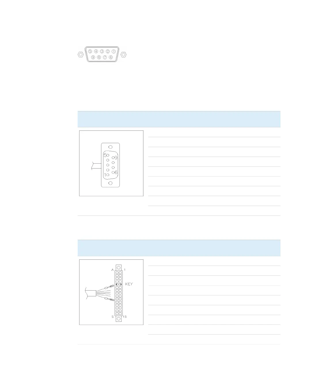
Agilent Module to General Purpose
p/n 5061-3378 Pin 35900 A/D Pin Agilent
module
Signal Name Active
(TTL)
1 - White 1 - White Digital ground
2 - Brown 2 - Brown Prepare run Low
3 - Gray 3 - Gray Start Low
4 - Blue 4 - Blue Shut down Low
5 - Pink 5 - Pink Not connected
6 - Yellow 6 - Yellow Power on High
7 - Red 7 - Red Ready High
8 - Green 8 - Green Stop Low
9 - Black 9 - Black Start request Low
p/n 01046-60201 Wire Color Pin Agilent
module
Signal Name Active
(TTL)
White 1 Digital ground
Brown 2 Prepare run Low
Gray 3 Start Low
Blue 4 Shut down Low
Pink 5 Not connected
Yellow 6 Power on High
Red 7 Ready High
Green 8 Stop Low
Black 9 Start request Low
 Loading...