Cabling Diagrams and Remote Start/Stop B
Agilent Intuvo 9000 GC Installation 101
APG Remote – Suggested drive circuits
A signal on the APG bus may be driven by another APG device
or by one of the following circuits:
• A relay, with one side connected to ground, when closed will
set a logic-low state.
• An NPN transistor, with the emitter connected to ground and
the collector connected to the signal line will set a logic-low
state if proper base current is supplied.
• An open-collector logic gate will perform this same function.
• A low-side drive IC will also work, but Darlington-type
drivers should be avoided as they will not meet the low-side
voltage requirement of less than 0.4 V
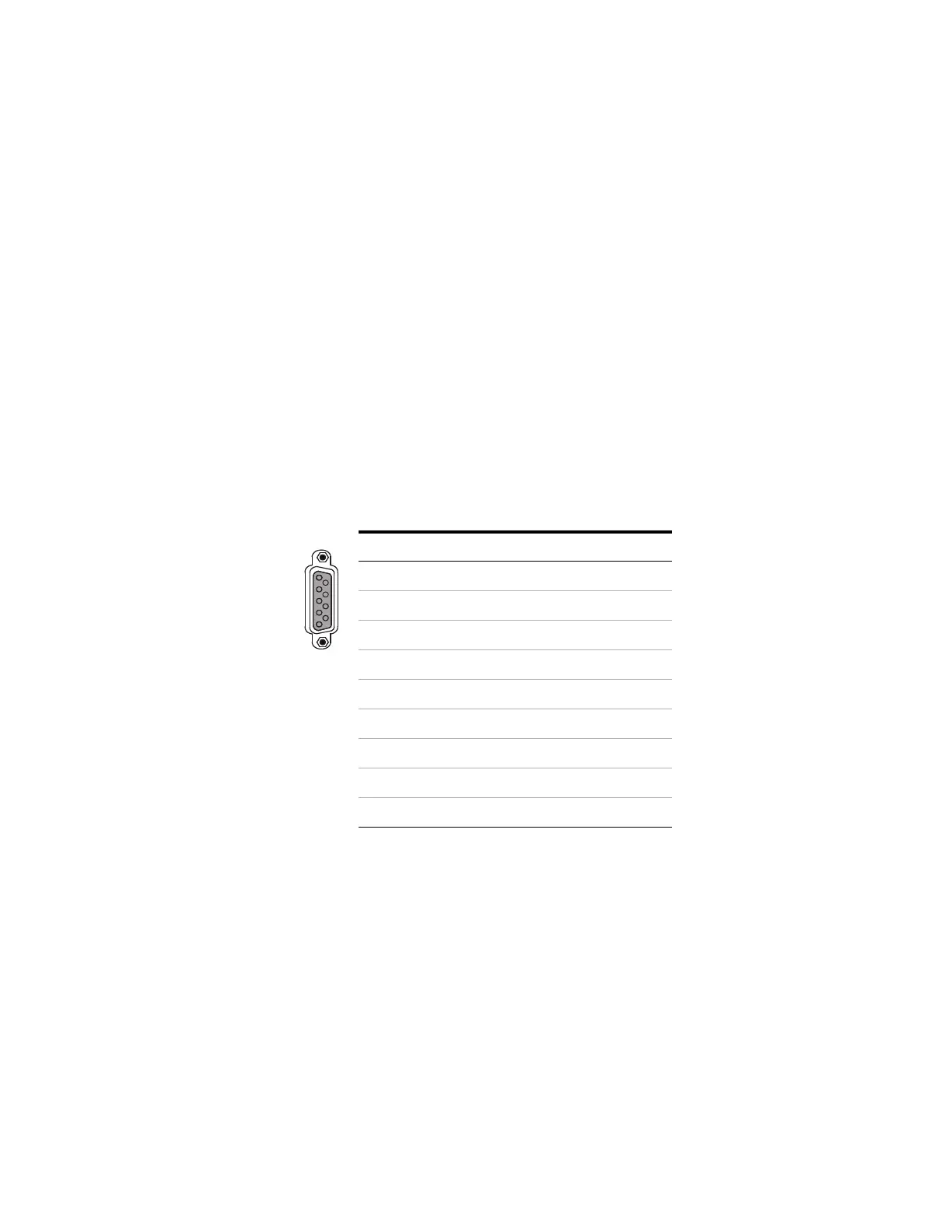
APG Remote connector
APG Remote signal descriptions
Prepare (Low True) Request to prepare for analysis. Receiver is
any module performing pre-analysis activities. For example,
shorting pin 2 to ground will put the GC into Prep Run state. This
is useful for Splitless Mode to prepare the inlet for injection or
when using Gas Saver. This function is not needed by Agilent
autosampler systems.
Ready (High True) If the Ready line is high (> 2.2 VDC) then the
system is ready for next analysis. Receiver is any sequence
controller.
Pin Function Logic
1 Digital ground
2Prepare LOW true
3 Start LOW true (output)
4Start relay
5Start relay
6Not used
7 Ready HIGH true (output)
8Stop LOW true
9Not used

 Loading...