34 Agilent Intuvo 9000 GC Installation
1 Installing the GC
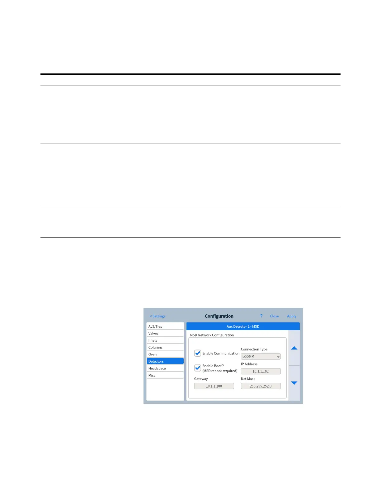
Configure the 5977B MS
If connected to a 5977B MS, use the GC touch screen to provide
the MS with its IP address, and to select the part information
(for example, source type and pump type). Touch Settings >
Configuration > Detectors, then select the tab for the MSD.
Scroll to the MSD Network Configuration settings to enter the MSD
IP address and related settings. The MSD IP address entered
here must exactly match the IP address entered in the data
system.
The GC already knows most details about the MSD, however,
3395B/3396C Integrator Remote, 9 pin/15 pin
Analog, 2 m, 6 pin
03396-61010
G1530-60570
Non-Agilent Integrator General purpose analog signal cable 2 m, 6 pin G1530-60560
Non-Agilent data system General use remote,
9-pin male/spade lugs
(various lengths)
35900-60670 (2 m),
35900-60920 (5 m),
35900-60930 (0.5 m)
Other devices
Non-Agilent
instrument, unspecified
External event, 8 pin/spade lugs (No label. See
“Labeling BCD and EVENT cables”.)
G1530-60590
Stream selection valves
Gas sampling valves (external)
See documentation accompanying the valve
External valve cable (includes green EVENT label) G1580-60710
LAN
LAN Cable, networking CAT 5, 25 feet
Cable, LAN, crossover
8121-0940
5183-4648
Table 4 Cabling requirements (continued)
9000 GC connected to: Required Cable(s) Part number
 Loading...