112 Agilent Intuvo 9000 GC Installation
B Cabling Diagrams and Remote Start/Stop
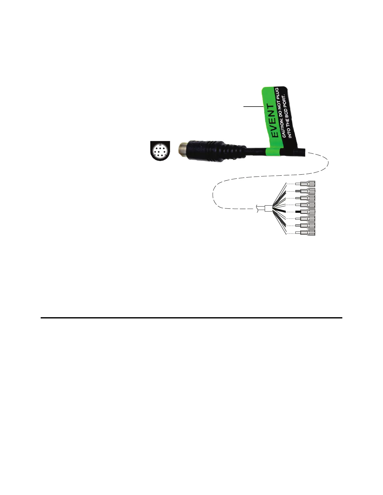
External event cable, G1530-60590
The external event cable has two passive relay contact closures
with two 24-volt control outputs. Devices connected to the
passive contact closures must be connected to their own power
sources.
The pin assignments for this cable are listed in Table 13.
4
5
6
3
12
78
Wire terminations
Apply label
G1580-87200
Table 13 External events cable
Connector 1 pin Signal name Maximum rating Connector 2, wire colorControlled by valve #
24 volts output
1 24 V output 1 150 mA Yellow 5
2 24 V output 1 150 mA Black 6
3Ground Red
4Ground White
Relay contact closures
(normally open)
5 Closure 1 48 V AC/DC, 250 mA Orange 7
6Closure 1 Green7
 Loading...