EasyManuals Logo
Home>Agilent Technologies>Laboratory Equipment>Intuvo 9000

Agilent Technologies Intuvo 9000 User Manual

Agilent Technologies Intuvo 9000
114 pages
To Next Page IconTo Next Page
To Previous Page IconTo Previous Page
Page #109 background imageLoading...
Page #109 background image
Cabling Diagrams and Remote Start/Stop B
Agilent Intuvo 9000 GC Installation 109
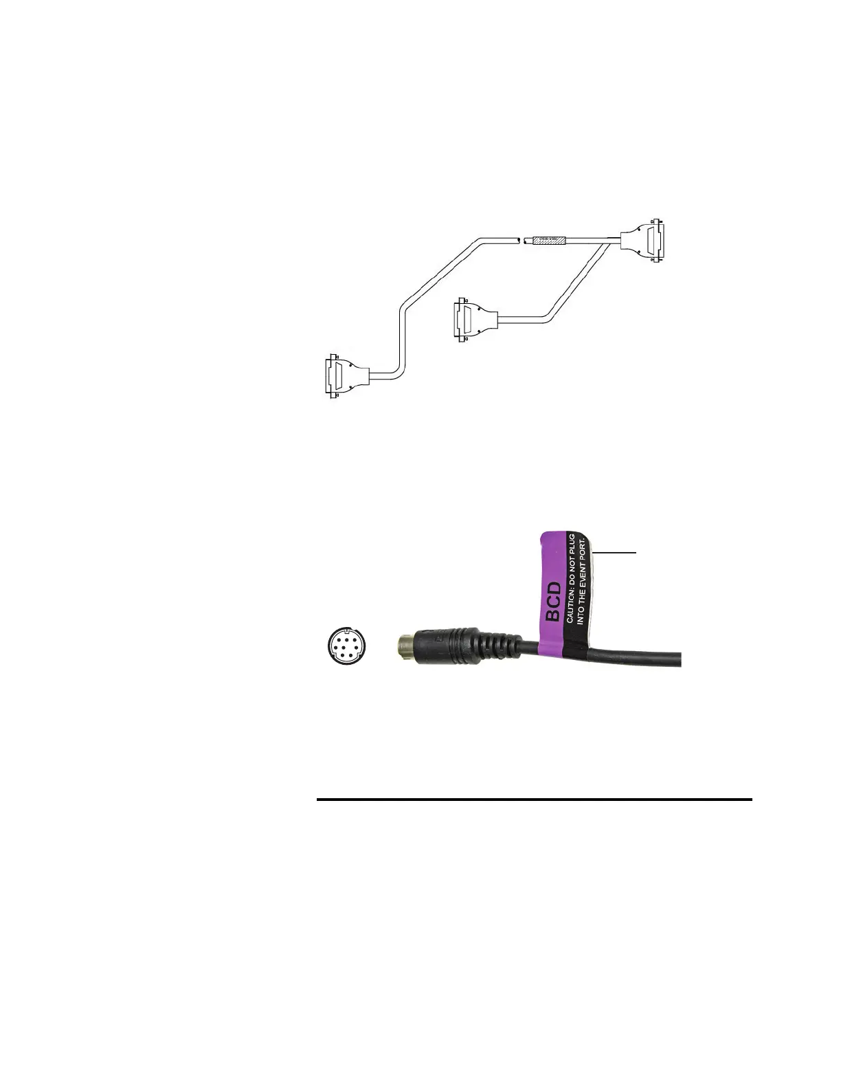
Agilent remote start/stop Y-cable, G1530-61200
Synchronizes the GC with another 2 Agilent instruments.
Figure 27 Remote start/stop cable, GC to Agilent instrument
BCD cable, G1530-60590
The BCD cable connector has eight passive inputs that sense
total binary-coded decimal levels. The pin assignments for this
connector are listed in Table 11.
Table 11 BCD input connections
Pin Function Maximum rating
1 Relay 48 V AC/DC, 250 mA
2 Relay 48 V AC/DC, 250 mA
3 LS digit 0
4 LS digit 1
5 LS digit 2
6 LS digit 3
Apply label
G1580-87100
2
8
1
6

Table of Contents

Other manuals for Agilent Technologies Intuvo 9000

Questions and Answers:

Question and Answer IconNeed help?

Do you have a question about the Agilent Technologies Intuvo 9000 and is the answer not in the manual?

Agilent Technologies Intuvo 9000 Specifications

General IconGeneral
BrandAgilent Technologies
ModelIntuvo 9000
CategoryLaboratory Equipment
LanguageEnglish

Related product manuals