EasyManuals Logo
Home>Agilent Technologies>Laboratory Equipment>Intuvo 9000

Agilent Technologies Intuvo 9000 User Manual

Agilent Technologies Intuvo 9000
114 pages
To Next Page IconTo Next Page
To Previous Page IconTo Previous Page
Page #113 background imageLoading...
Page #113 background image
Cabling Diagrams and Remote Start/Stop B
Agilent Intuvo 9000 GC Installation 113
When used for external event control, apply label G1580-87200
to identify the cable for EVENT use.
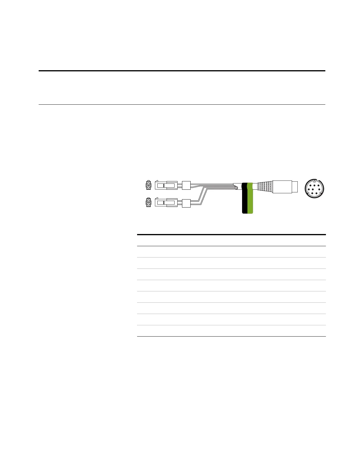
External valve cable, G1580-60710
Supplies power for certain valve applications.
7 Closure 2 48 V AC/DC, 250 mA Brown or violet 8
8Closure 2 Blue8
Table 13 External events cable (continued)
Connector 1 pin Signal name Maximum rating Connector 2, wire colorControlled by valve #
Connector 1 pin Wire color Connector and pin Function
1 Yellow V5 pin 1 24 V, 150 mA max.
2 Black V6 pin 1 24 V, 150 mA max.
3 Red V5 pin 2 Ground
4 White V6 pin 2 Ground
5
6
7
8
2
8
1
6
2
1
2
1
EVENT
CAUTION: DO NOT PLUG
INTO THE BCD PORT.
V5
V6

Table of Contents

Other manuals for Agilent Technologies Intuvo 9000

Questions and Answers:

Question and Answer IconNeed help?

Do you have a question about the Agilent Technologies Intuvo 9000 and is the answer not in the manual?

Agilent Technologies Intuvo 9000 Specifications

General IconGeneral
BrandAgilent Technologies
ModelIntuvo 9000
CategoryLaboratory Equipment
LanguageEnglish

Related product manuals