Installing the GC 1
Agilent Intuvo 9000 GC Installation 61
Connecting cables
Use the supplied LAN cable to connect the GC to a LAN switch
or hub as shown below (see “GC / MS / Agilent data system /
ALS”). Other LAN configurations are possible. However Agilent
typically supports only simple LAN setups. Refer to your
Agilent data system documentation for details about its
supported LAN configurations.
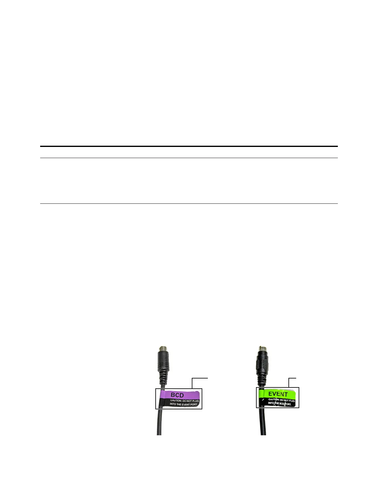
Labeling BCD and EVENT cables
The BCD and EVENT connectors look similar. However, plugging
an Event cable into the BCD connector can damage the GC logic
board. To prevent accidental damage, the following BCD and
Event cables come with labels that identify their intended use:
• G1580-60710, External valve cable
• G1580-60730, Pulser Module Power Supply Cable
• G1580-61100, BCD Cable Assembly
For other cables, apply an Event or BCD label to the cable:
• G1580-87100, Caution label, BCD cable, purple
• G1580-87200, Caution label, Events cable, green
Table 7 Cabling for other instruments in a 9000 GC system
Instrument 1 Instrument 2 Type of cable Part number
Mass Selective Detector Headspace sampler Splitter (“Y”) cable for remote
start/stop, 1 male and 2 female
connectors
G1530-61200
Splitter (“H”) cable for APG remote, 2
male and 2 female connectors
35900-60800

 Loading...