70 Agilent Intuvo 9000 GC Installation
1 Installing the GC
Install the Intuvo chips and column.
The GC ships with packing materials in the inlet base, column
connection, and column oven. Remove these and install the inlet
chip, Guard chip, and column.
Each GC ships with a simple D1 detector chip installed. If the
ordered configuration includes another detector, first verify the
D1 performance, then install the detector chip for the other
configuration and test. For an MS configuration with no other
GC detector, you will need to replace the simple D1 chip with
the MS chip before installing the column. Refer to the Intuvo
9000 GC Maintaining Your GC manual.
A capillary column was shipped with the GC to be used to
confirm proper operation. Agilent suggests that it be used only
for that purpose.
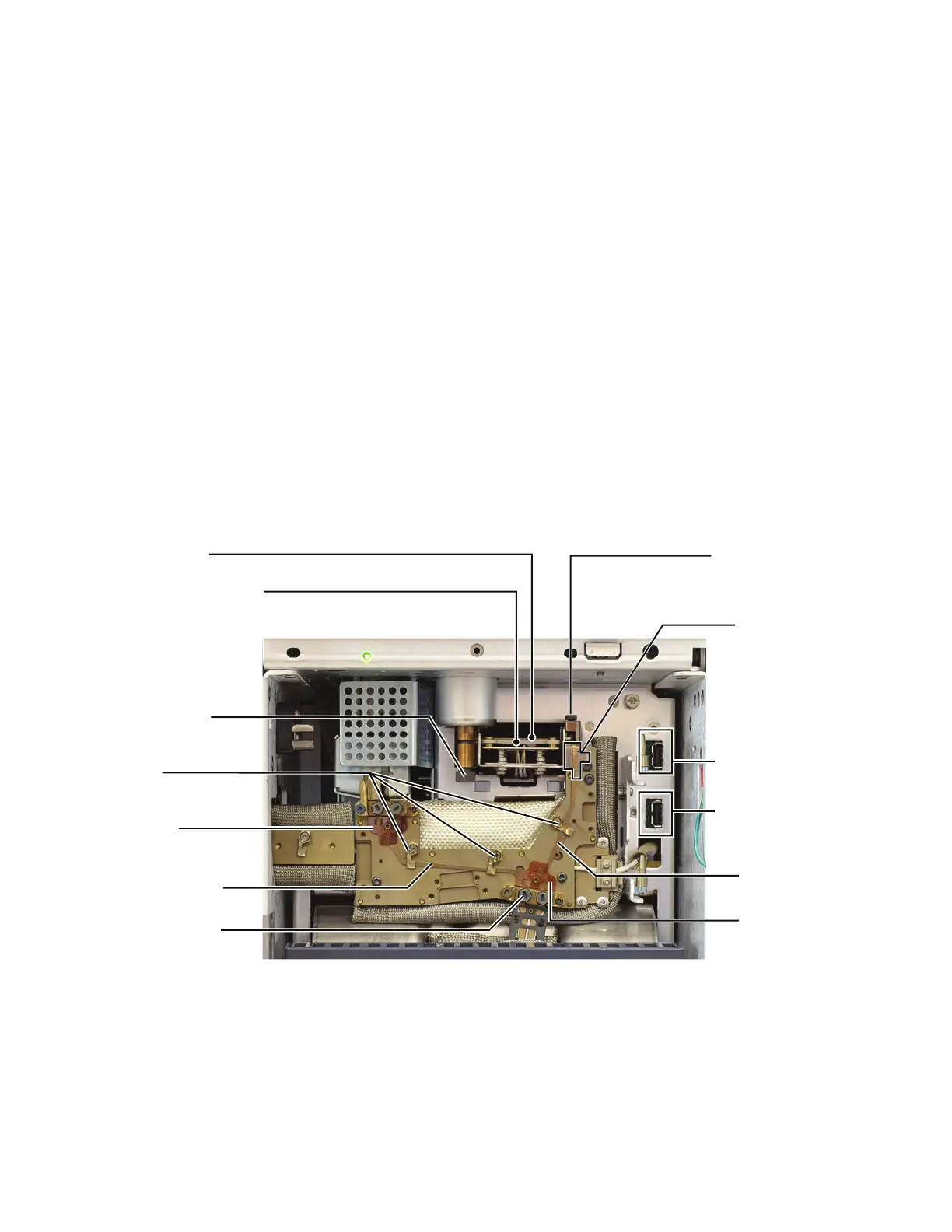
Figure 10 Intuvo GC bus components (split/splitless inlet with D1 chip
shown)
Inlet chip
Detector chip
Guard chip
Clips
Gasket
Gasket
Detector chip
Smart ID key
connector
Guard chip heater
Compression
bolt
Inlet sealing
screw
Guard chip
compression bolt
Inlet chip Smart
ID key connector
Little bus
 Loading...