Installing the GC 1
Agilent Intuvo 9000 GC Installation 33
addresses.
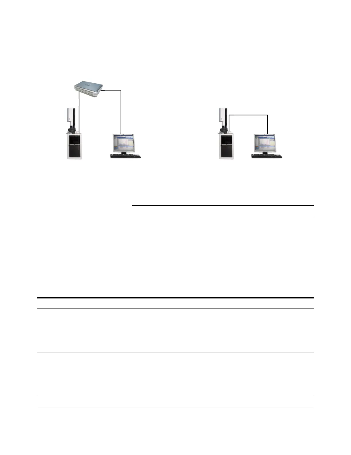
Figure 3 Simple supported LAN configurations: LAN switch or hub (left) and direct connection (right)
A single LAN communications cable is supplied with the GC.
The switch (or hub) and other cables must be ordered
separately, if needed. See Table 3 and Table 4 for cabling
requirements for other configurations.
LAN switch or hub
LAN cable
8121-0940
Crossover LAN cable 5183-4648
GC GCComputer Computer
LAN cable
8121-0940
OR
Table 3 Typical IP addresses for an isolated LAN
GC Computer
IP address 10.1.1.101 10.1.1.100
Subnet mask 255.255.255.0 255.255.255.0
Table 4 Cabling requirements
9000 GC connected to: Required Cable(s) Part number
Samplers
7693A Automatic Liquid Sampler Injector cable or tray cable G4514-60610
7650 Automatic Liquid Sampler Injector cable G4514-60610
7697A Headspace Sampler Remote, 9-pin male/6-pin connector G1530-60930
G1289B/G1290B Headspace Sampler Remote, 9-pin male/6-pin connector G1530-60930
PAL automatic sampler Cable, 4 conductor, remote start G6500-82013
Mass Spectrometers and MS systems
Mass Selective Detector Remote, 2-m, 9-pin male/9-pin male G1530-60930
Integrators

 Loading...