Use and Maintenance Manual - X_RT Series Page 11
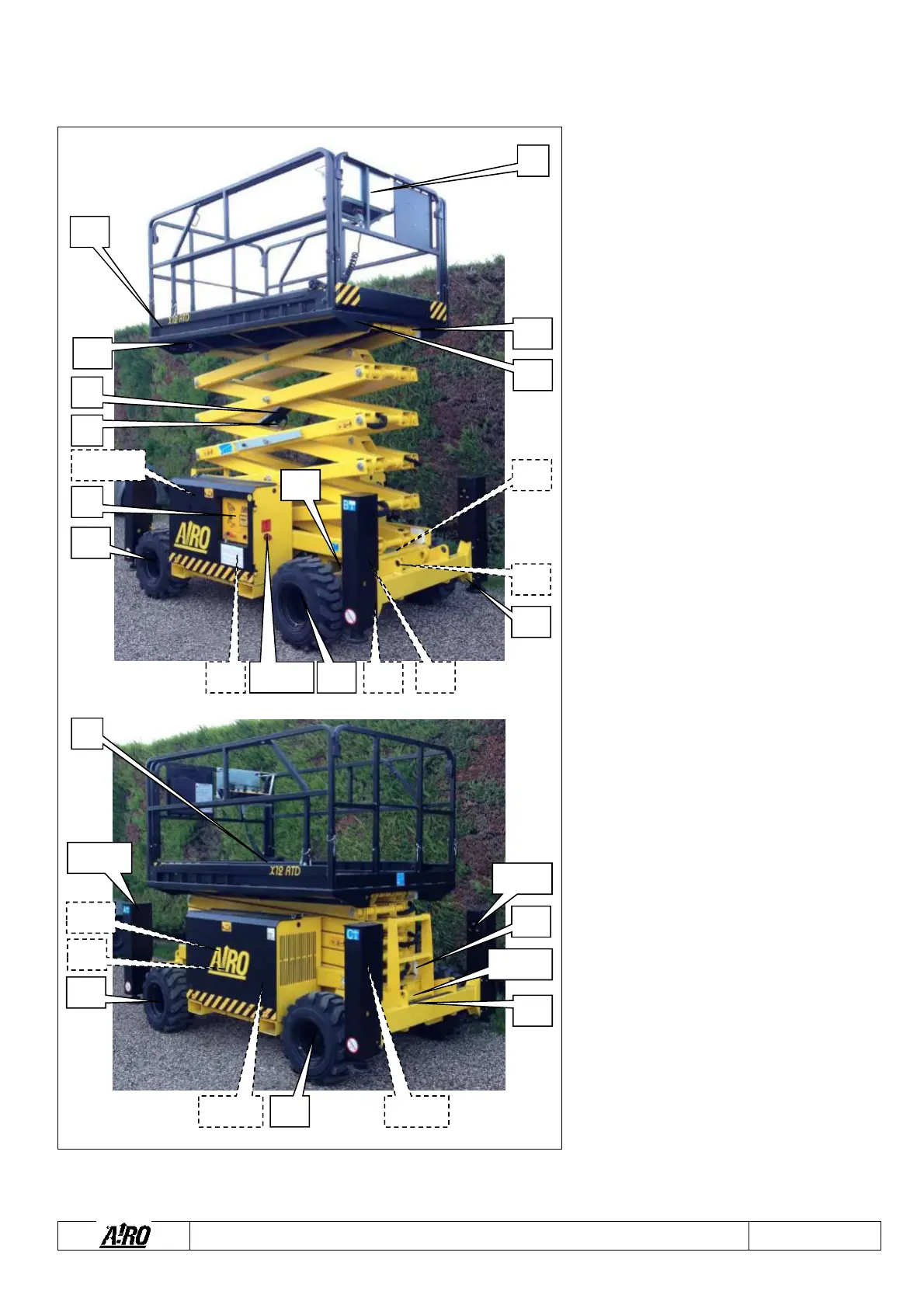
1.9 Location of main components
The picture shows the machine and its
components.
1) Platform control panel
2) Spirit level (standard for models with
levelling outriggers; optional for the other
models) for visual check of machine
levelling
3) Lifting cylinders
4) Lowering control valve
5) Ground control station
6) Electric control unit and inclinometer
7) Hydraulic oil tank
8) Diesel tank (models "RTD")
9) Electric Pump (models “RTE”)
10) Diesel Engine (models "RTD")
11) Platform height control M1 microswitch
12) Oscillating axle control M13 microswitch
13)
230V eectric ie pug (ptia)
14) Circuit breaker (optional)
15) Overload controller sensors
16) Starter battery (models “RTD”)
17) Electric Pump (models “RTE”)
18) Electric Pump (models “RTE”)
19) Hydraulic drive motors
20) Hydraulic control unit
21) Steering cylinder
22) Manual device for emergency lowering
23) Levelling outriggers (optional)
24) Levelling outrigger control solenoid valves
(optional)
25) High position levelling outrigger control
sensor (optional)
26) Low position levelling outrigger control
microswitch (optional)
27) Power Switch (models “RTD”)
28) Battery isolator connector (models “RTE”).
21
2
11
17 18 23 24
8 9
10
19
19
22
2324
13 14
23 24
1
4
19
13
21
15
25 26
5
3
12
16
6 7 20
15
15
19
25
27 28