Use and Maintenance Manual - X_RT Series Page 66
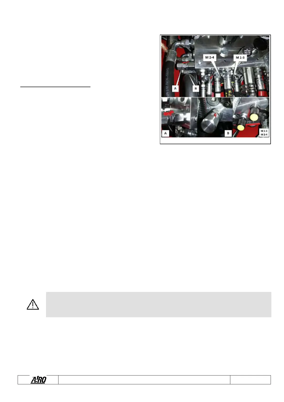
7.3.7 Pressure relief valve adjustment and operation check
The pressure relief valves (A -B) control the maximum pressure of the
hydraulic circuit. Normally, this valve does not require any adjustment,
since it is calibrated at the factory before the machine is delivered.
The pressure relief valve must be calibrated in the following cases:
in case of replacement of the hydraulic block
In case of replacement of the pressure relief valve only
Check operation at least once a year.
To check the operation of the main pressure relief valve (see figure
aside) – For Valve A:
Introduce a pressure gauge with full scale of at least 300 bar in the
special quick coupling (1/4” BSP) marked M1-3.
Locate the pressure relief valve A.
Disconnect the power cord of the traction solenoid valves EV2 and
EV3;
Using the platform control panel set to drive with the machine
forwards or backwards at first speed at the start of the driving
operation in order to accelerate the Diesel engine but with the machine in a stationary position and operating the steering up to
the end stop at the same time.
Check the pressure value. The correct value is indicated in the chapter “Technical features”.
In case of need, to calibrate Valve A:
Unscrew the adjusting dowel lock-nut.
Work on the adjusting dowel while executing the commands previously described.
Once calibration has been carried out, lock the adjusting dowel by means of the lock-nut.
To check the operation of the main pressure relief valve (see figure aside) - For Valve B:
Introduce a pressure gauge with full scale of at least 300 bar in the special quick coupling (1/4” BSP) marked M2-4.
Locate the pressure relief valve B.
Disconnect the power cord of the traction solenoid valves EV2 and EV3;
Using the platform control panel set to forward or backward drive at second speed control the traction (the platform will remain
locked) with joystick to maximum.
Check the pressure value. The correct value is indicated in the chapter “Technical features".
In case of need, to calibrate Valve B:
Unscrew the adjusting dowel lock-nut.
Work on the adjusting dowel while executing the commands previously described.
Once calibration has been carried out, lock the adjusting dowel by means of the lock-nut.
WARNING!
AS THIS OPERATION IS VERY IMPORTANT IT IS TO BE CARRIED OUT BY SKILLED TECHNICIANS ONLY.
Fig. 27