7705 SAR-A Connectors and LEDs
120 7705 SAR-A Chassis Installation Guide
7705 SAR-A Connectors and LEDs
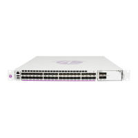
Figure 28 identifies the connectors and LEDs on the front of the router. The variant shown is
equipped with T1/E1 ports.
Figure 28: 7705 SAR-A Connectors and LEDs (Variant with T1/E1 Ports)
Table 28 describes the connectors and LEDs on the 7705 SAR-A.
7705 SAR-A
Mgmt
ToD Out
Lnk Act
Sync
In
+Batt A
-Batt A
+Batt B
-Batt B
Console
812111097654B3B2B1B1A
Status
2A 3A 4A
ActLnk ActLnk ActLnk ActLnk
Stat Stat Stat Stat
2468
1357
Lnk Act Lnk Act Lnk Act Lnk Act
Stat Stat Stat Stat
T1/E1Ethernet
-48 VDC
23334
1
3 5 6 9
2 4 7 8
Table 28: 7705 SAR-A Connector and LED Descriptions
Key Label/Part Sub-
category
Description
1 Ethernet Ports SFP ports Ports 1B to 4B and ports 5 to 8 are SFP ports. The SFP port number is
displayed below each port.
RJ-45
connectors
Four Gigabit Ethernet ports have RJ-45 connectors that are numbered 1A
to 4A. The RJ-45 ports numbered 9 to 12 support Fast Ethernet. The port
numbers are displayed below each port. The associated Lnk (link) LED
is located at the top-left corner of the port, and the associated Act
(activity) LED is located at the top-right corner of the port.
Lnk LED Green: Indicates that the link is up
Unlit: Indicates that there is no link, or that the link is operationally
down, disabled or shut down
Act LED Amber (blinking): Indicates that the port is active (receiving or
transmitting)
Unlit: Indicates that the port is down or disabled
 Loading...


