Installing the IOM-a
114 7750 SR-a4 and SR-a8 Installation Guide
Installing the IOM-a
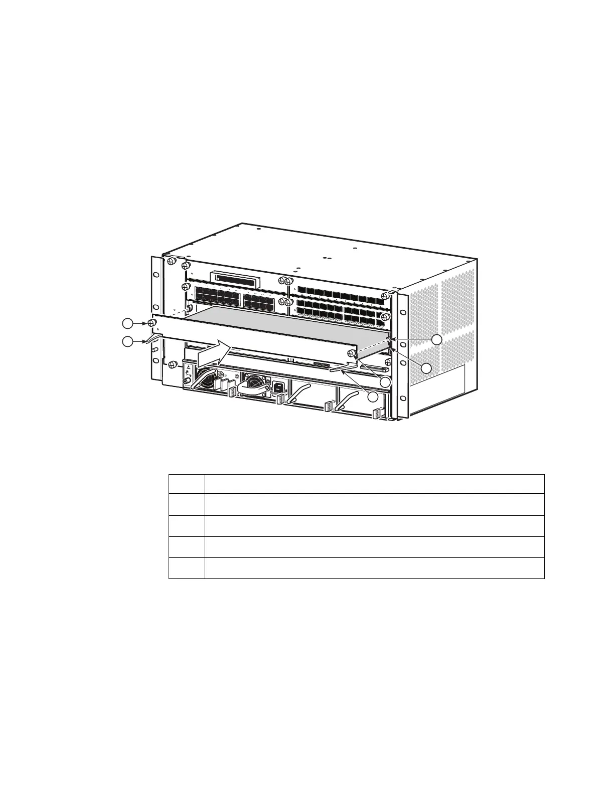
The 7750 SR-a4 has one IOM-a in slot 3, as shown in Figure 38. The 7750 SR-a8 has up to
two IOM-a cards, one in slot 3, the other in slot 6. Table 51 describes the installation features;
the features apply to both chassis.
Figure 38: Installing an IOM-a
Required tools:
• #2 Phillips or flat blade torque driver
To install an IOM-a:
7750 SR
-
a4 F
an
Tra y
P
w
r
S
t
at
S
l
o
t
L
ay
o
u
t
1
/
1
X
P
1
/
2
1
/
3
1
/
4
1
C
P
M
A
C
P
M
B
7
750 SR-a
4
S
e
r
vice
Ro
u
te
r
P
w
r
S
tat
P
wr
7
7
5
0
MD
A-a
X
P
1
-
1
0
0
G
E
-
C
F
P
S
t
at
Lnk
P
w
r
7
7
5
0
MDA
-
a
2
0
-
1
G
B-
TX
S
t
at
L
n
k
1
Act
2
L
n
k
3
A
ct
4
L
n
k
5
Act
6
L
n
k
7
Act
8
L
n
k
9
Act
10
L
n
k
11
Act
12
L
n
k
13
Ac
t
14
L
n
k
15
Act
16
L
n
k
17
A
ct
18
L
nk
19
Act
20
Sy
nc
E1
/5
8
8
A
larm
s
1
P
P
S
A
C
O
L
T
C
r
i
t
i
c
a
l
Lnk
DTE
P
w
r
7
7
5
0
CP
M-
a
S
t
at
Co
n
so
l
e
M
gmt O
ES
B
I
T
S
C
om
pact
Fl
ash
D
CE
Ac
t
Lnk Ac
t
M
a
j
or Mi
nor
Sy
n
c
E1
/5
8
8
A
larm
s
1
P
P
S
A
CO
L
T
C
r
i
t
i
c
a
l
Lnk
D
TE
P
w
r
7
7
5
0
C
P
M-a
St
at
Co
n
so
l
e
M
gmt
O
E
S
B
I
T
S
C
om
pact
Fl
ash
D
CE
Ac
t Lnk A
c
t
M
a
j
or
Minor
P
wr
S
t
a
t
7
7
5
0
M
D
A
-
a
XP
1
0
-
1
0
G
B-
S
FP
+
1
0
Lnk
A
c
t
9
Lnk
A
c
t
8
Lnk
A
c
t
7
Lnk
A
c
t
6
Lnk A
ct
5
Lnk
Act
4
Lnk
A
ct
3
Lnk
Ac
t
2
Lnk
Act
1
Lnk Act
P
w
r
7
7
5
0
M
DA-a
4
4
-
1
G
B-
CS
FP
/
S
FP
S
t
a
t
L
n
k
/
A
c
t
1
2
3
4
5
6
7
8
9
1
0
1
1
1
2
1
3
1
4
1
5
1
6
2
5
2
6
2
7
2
8
2
9
3
0
3
1
3
2
3
3
3
4
3
5
3
6
3
7
3
8
3
9
4
0
4
1
4
2
4
3
4
4
1
7
1
8
1
9
2
0
2
1
2
2
2
3
2
4
P
w
r
7750
S
R-
a
S
t
at
Air
F
ilt
er
A
c
c
es
s
7
7
50
S
R
-a
4
1
2
3
4
3
4
24560
Table 51: Installing an IOM-a Features
Key Description
1 IOM-a positioned in the chassis slot guides
2 Threaded receptacle on the chassis
3 IOM-a captive screws, one on each side of the IOM-a
4 Ejector lever, one on each side of the IOM-a (in open position)