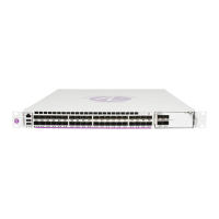
Installing a 7750 SR-a Chassis Horizontally in a Rack
78 7750 SR-a4 and SR-a8 Installation Guide
Figure 18: Installing the 7750 SR-a8 Chassis in a 19-in. (482.6 mm) EIA-310 Rack
Required tools:
7
75
0
S
R-a8
Se
r
vice R
outer
A
ir
F
ilt
er
Ac
c
e
s
s
7
750
S
R
-a8
24549
1
3
4
2
Table 35: Rack Mounting Parts: 19-in. (482.6 mm) EIA-310 Rack
Key Description
1 19-in. (482.6 mm) equipment rack rail
2 Screws used temporarily to support the bottom edge of the rack-mounting flange
during chassis installation. Screws are partially installed in the equipment rack
rail in the lowest allocated U-space on both sides of the rack unit.
3 Integrated rack-mounting flange on the chassis. Flanges cannot be removed.
4 Eight rack-mounting screws (screws not included)

 Loading...


