Installing the 7750 SR-a Chassis
7750 SR-a4 and SR-a8 Installation Guide 83
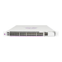
Figure 22: Installing the 7750 SR-a8 Chassis in the ETSI Rack
Required tools:
7
75
0
S
R-a8
Se
r
vice R
outer
A
ir
F
ilt
e
r
A
c
c
e
s
s
7
750
S
R
-a8
24657
4 3 2
1
Table 37: Rack Mounting Parts: ETSI Rack with Adapters
Key Description
1 ETSI equipment rack rail
2 Screws used temporarily to support the bottom edge of the ETSI brackets during
chassis installation. Screws are partially installed in the rack rail in the lowest
allocated U-space on both sides of the rack unit.
3 ETSI brackets (installed on chassis, as described in Attaching the Adapter
Brackets to the Chassis on page 80). The oval (unthreaded) mounting holes are
used to attach the adapter bracket to the rack.
4 Eight screws to attach the ETSI adapter bracket to the equipment rack (screws not
included)

 Loading...


