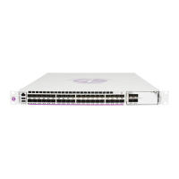
7750 SR-a Chassis Features
26 7750 SR-a4 and SR-a8 Installation Guide
7750 SR-a4 Chassis Slot Allocation
This section describes the slot allocations for each type of chassis component. Figure 2
identifies the slots and the components.
Figure 2: 7750 SR-a4 Chassis Slot Identification
As shown in Figure 2, slots 1 to 3 make up the 7750 SR-a4 forwarding complex. The
forwarding complex has a single IOM-a and up to four MDA-a cards with a total forwarding
capacity of 100 Gb/s.
MDA-a and MDA-aXP cards occupy a half of a chassis slot. Slot one (at the top of the
chassis) supports up to two MDA-a cards. Slot two also supports up to two MDA-a cards. The
adapter cards are numbered individually as MDA-a 1/1, MDA-a 1/2, MDA-a 1/3, and MDA-
a 1/4.
MDA-a slot 1/1 and 1/2 are XP-capable, meaning that they support 100 Gb/s MDA-aXPs.
These slots support up to 100 Gb/s full-duplex bandwidth. The remaining two MDA-a slots
support 25 Gb/s full-duplex bandwidth. MDA-a cards must be ordered separately from the
chassis. An impedance panel must be installed in any empty MDA-a slot. See MDA-a Cards
for more information.
MDA-XP 1/1
Fan Tray
IOM 1
MDA-XP 1/2
MDA 1/3 MDA 1/4
CPM A
PSU 1 PSU 2 PSU 3 PSU 4
CPM B
Slot 1
Slot 2
Slot 3
Air Filter
Slot 4
24538
Forwarding
Complex
Note:
• A 100 Gb/s MDA-aXP card can operate in a 25 Gb/s slots, but the slot will be
oversubscribed. If you install a 100 Gb/s MDA-aXP card in a 25 Gb/s slot, the maximum
line rate is 25 Gb/s.
• A 25 Gb/s MDA-a card can operate in 100 a Gb/s slot, but the slot will be
undersubscribed. If you install a 25 Gb/s MDA-a card in a 100 Gb/s slot, the maximum
line rate is 25 Gb/s.

 Loading...


