Installing MDA-a and MDA-aXP Cards
116 7750 SR-a4 and SR-a8 Installation Guide
Installing MDA-a and MDA-aXP Cards
The term MDA-a is used generically in this section to refer to MDA-a and MDA-aXP cards.
For information about the MDA-a cards that are supported in the 7750 SR-a4 and 7750 SR-a8
chassis and the slots in which the cards are supported, see MDA-a Cards on page 36.
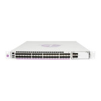
Figure 39 and Figure 40 show the installation of an MDA-a. Table 52 describes the
installation features.
Figure 39: Installing an MDA-a (7750 SR-a4)
7750 SR
-
a4 F
an
Tra y
Pwr
S
tat
S
l
ot
Layout
1/1
X
P
1/2
1/
3
1/4
1
C
P
M
A
C
P
M
B
7
750 SR
-a4
Se
rvice Ro
uter
P
wr
S
tat
P
wr
7
7
5
0
MD
A
-aX
P
1
-
1
0
0
G
E
-
C
F
P
S
t
a
t
Lnk
P
w
r
7
7
5
0
MDA-a
2
0
-
1
G
B-
TX
S
t
at
L
n
k
1
Act
2
L
n
k
3
Act
4
L
n
k
5
Act
6
L
n
k
7
Act
8
L
n
k
9
A
ct
10
L
nk
11
Act
12
L
n
k
13
Act
14
L
n
k
1
5
Act
16
L
n
k
17
A
ct
18
L
n
k
19
Act
2
0
P
w
r
7750
SR
-
a
S
tat
Pw
r
7
7
5
0
M
DA-a
4
4
-
1
G
B-
CS
FP
/
S
FP
S
t
a
t
L
n
k/
A
ct
1
2
3
4
5
6
7
8
9
10
1
1
12
13
14
1
5
16
25
26
27
28
29
3
0
31
32
33
34
35
36
37
38
39
40
41
42
43
44
17
18
19
20
21
22
23
2
4
P
w
r
S
t
at
7
7
5
0
MD
A-a
X
P
1
0
-
1
0
G
B-
S
FP
+
1
0
Lnk
Act
9
Lnk A
ct
8
Lnk Act
7
Lnk
Act
6
Lnk A
ct
5
Lnk A
ct
4
Ln
k
A
ct
3
Lnk Act
2
Lnk A
ct
1
Lnk
A
c
t
Sy
ncE/15
8
8
Ala
rm
s
1P
P
S
AC
O
/LT
C
r
iti
cal
Lnk
DTE
P
wr
7
7
5
0
C
P
M-a
S
t
a
t
C
on
s
ole
M
g
m
tO
ES
B
I
TS
C
om
pact Flash
DCE
A
ct
Lnk Act
M
a
j
or
M
i
n
or
Sy
n
c
E/1
5
8
8
A
l
arms
1PP
S
ACO/LT
Cr
i
t
i
cal
Lnk
D
TE
Pw
r
7
7
5
0
C
P
M-a
S
tat
Co
nsole
M
gmt
O
E
S
B
I
TS
C
ompact Flash
D
C
E
Act Lnk A
ct
M
aj
or
Minor
Air
F
ilt
er
A
c
c
es
s
77
5
0
S
R
-a
4
1
3
2
2
24561

 Loading...


