Removing and Replacing a Fan Tray
186 7750 SR-a4 and SR-a8 Installation Guide
Removing a Fan Tray
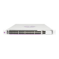
Figure 66 shows how to remove the fan tray from the 7750 SR-a4 chassis. Table 94 describes
the features. The same method applies to the fan tray in the 7750 SR-a8 chassis.
Figure 66: Removing the Fan Tray (7750 SR-a4)
Required tools:
• #2 Phillips or flat blade screwdriver
To remove the fan tray:
Step 1. Unpack the replacement fan tray from the protective packaging. Place the fan tray
on an antistatic surface.
Step 2. To remove the fan tray from the chassis, use a screwdriver to loosen the captive
screws on the fan tray faceplate.
Step 3. Grip the two captive screws (Key 1 in Figure 66), and pull the fan tray halfway out
of the chassis and allow the fans to stop spinning.
7750
S
R
-
a4 Fan T
r
a
y
Pw
r
Stat
S
lot
Lay
ou
t
1
/
1
X
P
1/
2
1/
3
1/
4
1
CP
M
A
C
P
M
B
77
5
0
SR-a
4
S
e
r
vice
Ro
u
te
r
7750
SR
-
a4 Fan T
r
ay
P
w
r
S
t
at
S
l
o
t
L
ayo
u
t
1
/
1
X
P
1
/
2
1
/
3
1
/
4
1
CP
M
A
CP
M
B
P
w
r
S
t
a
t
P
w
r
7
7
5
0
MD
A
-
a
X
P
1
-1
0
0
G
B
-
C
F
P
S
t
a
t
Lnk
P
w
r
7
7
5
0
MDA-a
2
0
-
1
G
B-
TX
S
t
a
t
L
n
k
1
A
c
t
2
L
n
k
3
A
c
t
4
L
n
k
5
Ac
t
6
L
n
k
7
A
c
t
8
L
nk
9
Ac
t
10
L
n
k
11
Ac
t
12
L
n
k
13
Ac
t
14
L
n
k
15
A
c
t
16
L
n
k
17
Ac
t
18
L
n
k
19
A
c
t
20
Sy
n
c
E/15
8
8
A
larm
s
1
P
P
S
A
C
O
/
LT
Cr
i
t
i
c
a
l
Lnk
DTE
P
wr
7
7
5
0
CP
M
-
a
S
t
a
t
Co
n
so
l
e
M
gmt
O
E
S
B
I
TS
C
om
pact
Fl
ash
DCE
Act L
n
kAc
t
Ma
j
or Mi
nor
Sy
n
c
E/1
5
8
8
A
l
ar
m
s
1
P
P
S
A
CO/
LT
C
r
i
t
i
c
a
l
Ln
k
D
T
E
P
w
r
7
7
5
0
C
P
M
-
a
St
a
t
Co
n
s
o
l
e
M
gmt
O
E
S
B
I
TS
C
om
pact
Fl
a
sh
D
CE
Ac
t
Lnk Ac
t
M
a
j
or M
i
nor
P
wr
7750
SR
-
a
S
t
at
P
w
r
S
t
a
t
7
7
5
0
M
D
A
-
a
XP
1
0
-
1
0
G
B-
S
FP
+
10
Lnk Ac
t
9
Lnk A
c
t
8
Ln
k
A
c
t
7
Ln
k
A
c
t
6
Lnk A
c
t
5
Ln
kAc
t
4
Lnk
A
c
t
3
Lnk
A
c
t
2
Lnk
Act
1
Ln
kAct
Pwr
7
7
5
0
M
DA-a
4
4
-
1
G
B-
CS
FP
/
S
F
P
S
t
a
t
L
n
k
/
Ac
t
1
2
3
4
5
6
7
8
9
10
11
1
2
1
3
1
4
15
16
25
26
27
28
29
30
31
32
33
34
3
5
36
3
7
38
39
40
41
42
43
44
17
18
19
20
2
1
22
23
24
A
ir
F
ilt
er
Ac
c
es
s
7
75
0
S
R
-a4
24585
Pwr
7
7
5
0
CP
M
-
a
S
t
at
7750
SR
-
a4 Fan T
r
ay
P
w
r
S
t
at
S
l
o
t
L
ayo
u
t
1
/
1
X
P
1
/
2
1
/
3
1
/
4
1
CP
M
A
CP
M
B
1
1
Table 94: Fan Tray Removal Features
Key Description
1 Captive screws

 Loading...


