4. Interfacing to the world 44
Pin Name Function
1 P0- Bidirectional port, negative input
2 P0+ Bidirectional port, positive input
3 P1- Input port, negative input
4 P1+ Input port, positive input
5 GND Ground
6 DC Out DC Output - 300 mA max
7 P3- Output port, negative output
8 P3+ Output port, positive output
9 P2- Input port, negative input
10 P2+ Input port, positive input
11 P4- Output port, negative output
12 P4+ Output port, positive output
Table 4.1: I/O Connector pinout
The I/O ports are disabled at power-on, to disconnect any external load and user termination whose
power consumption may exceed the USB 3.2 Gen 1x1 standard requirements during the bus recognition
and enumeration phase. The I/O ports are automatically enabled at the end of the USB enumeration
phase.
4.0.1 Detecting I/O power
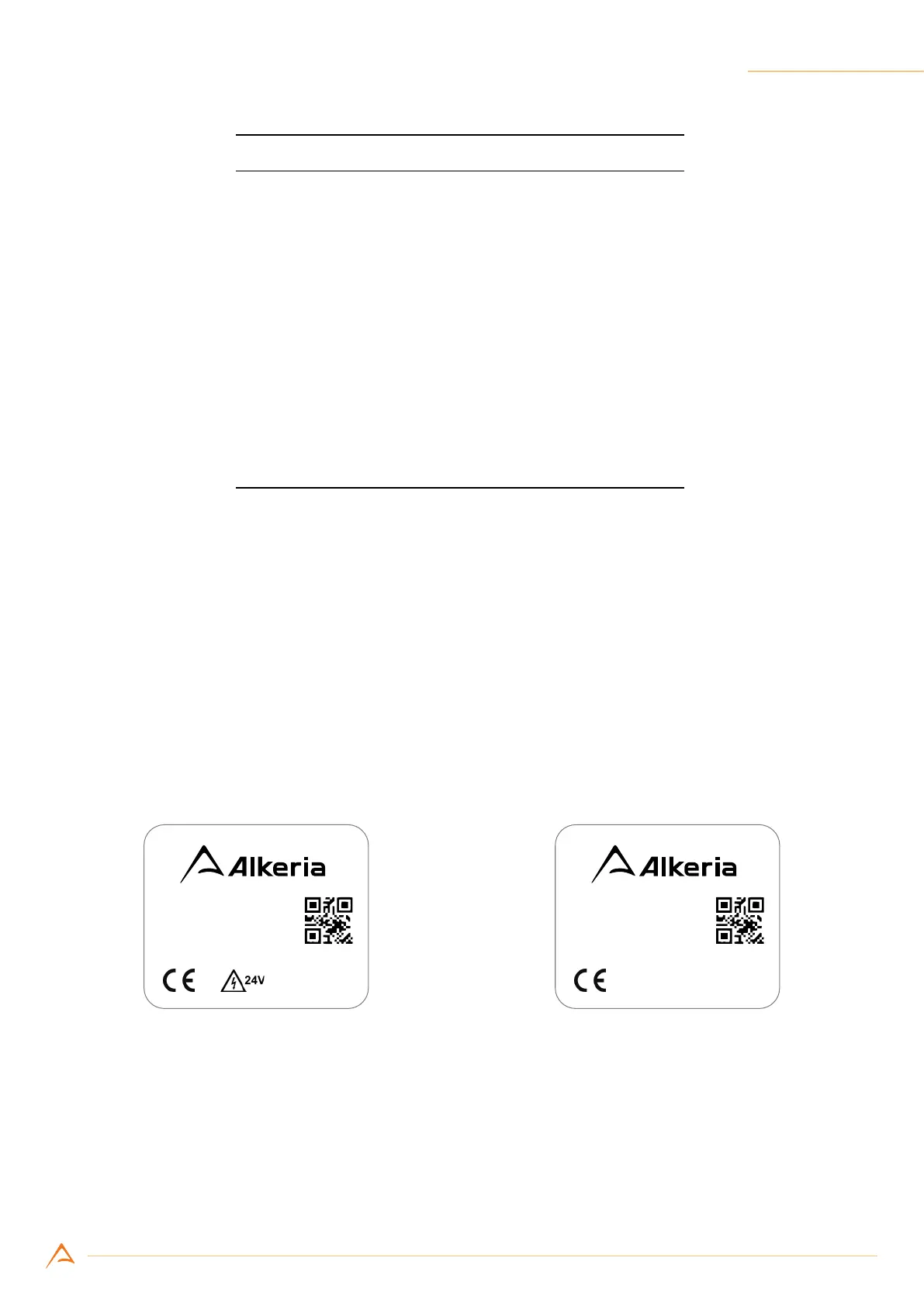
NECTA features a 24 V tolerant I/O interface. However, previous NECTA hardware releases tolerates
only 5 V signaling: for this reason, on each camerathis feature is specied on the label, in order to quickly
identify which model is compatible with 24 V signals.
S/N 1234567A
NECTA
N4K2-7C
Made in Italy
(a) NECTA with 24 V tolerant I/O
S/N 1234567A
NECTA
N4K2-7C
Made in Italy
(b) NECTA with 5 V tolerant I/O
Figure 4.2: Differences between NECTA labels