4. Interfacing to the world 58
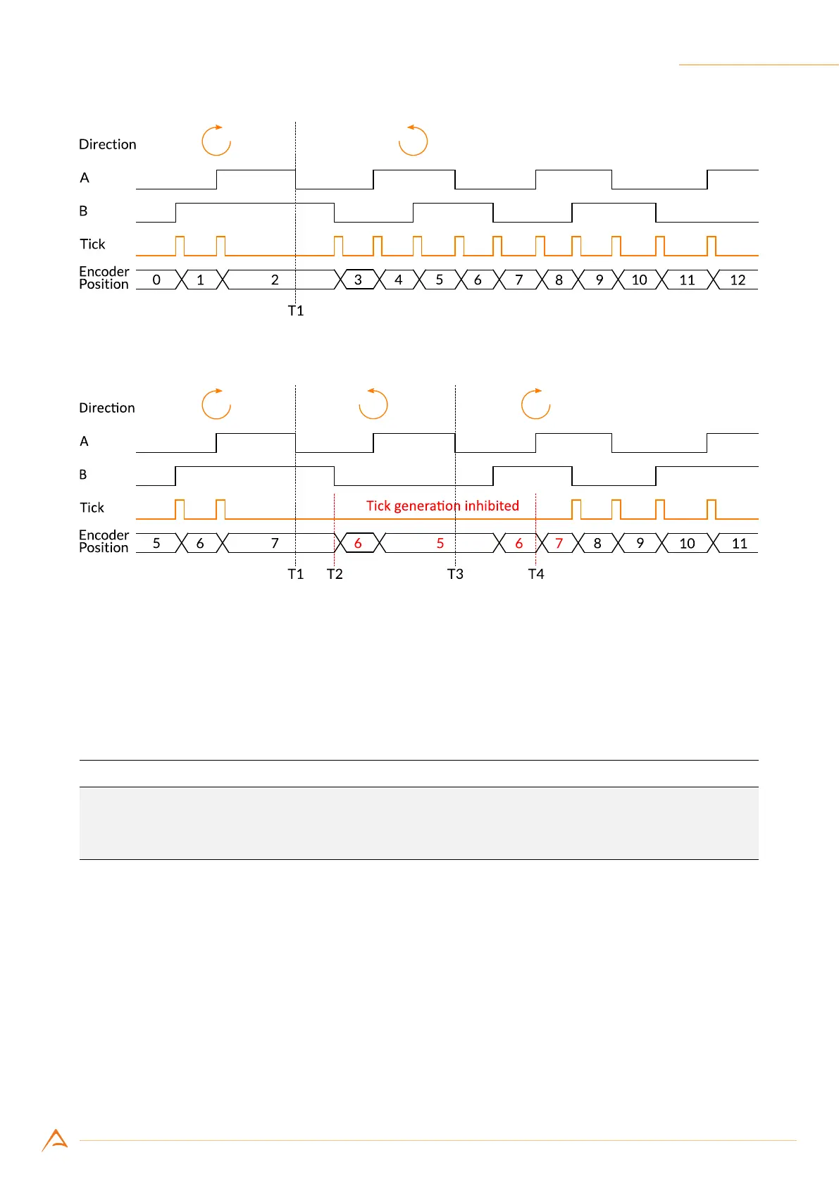
Figure 4.20: Ticks generated when ignore direction is enabled
Figure 4.21: Ticks generated when ignore direction is disabled
4.4.1.3 Conguring the encoder module
The following code sets the input ports 1 and 2 as the phase (A) and quadrature (B) encoder inputs. The
encoder module is programmed to generate a trigger only when rotating in the positive direction.
Example Code 4.3 | Encoder ports conguration
device.Encoder.InputA = 1;
device.Encoder.InputB = 2;
device.Encoder.IgnoreDirection = false;
4.4.1.4 Reading and resetting encoder position
The current encoder position can be read at any time as a 32-bit unsigned integer. The returned value
is the last value of the encoder module position counter at the time of the request.
The encoder module position can be read and reset to 0 via software or with an external signal.
The following example shows how to reset encoder via software: