4. Interfacing to the world 56
Warning
Input signals are usually processed by the debouncing module (see Section
4.3.1.1), which avoids false acquisitions when the input signals may contain
glitches. However, the debouncing module obviously limits the input signal
bandwidth: when an input signal is changing very fast, properly setting the
related debouncing module, or even disabling it, may be necessary to avoid
losing events.
4.4 USING INPUT SIGNALS
Input signals
3 3
Debouncer
Encoder
Freq Mult
Trigger manager
UART
Input status
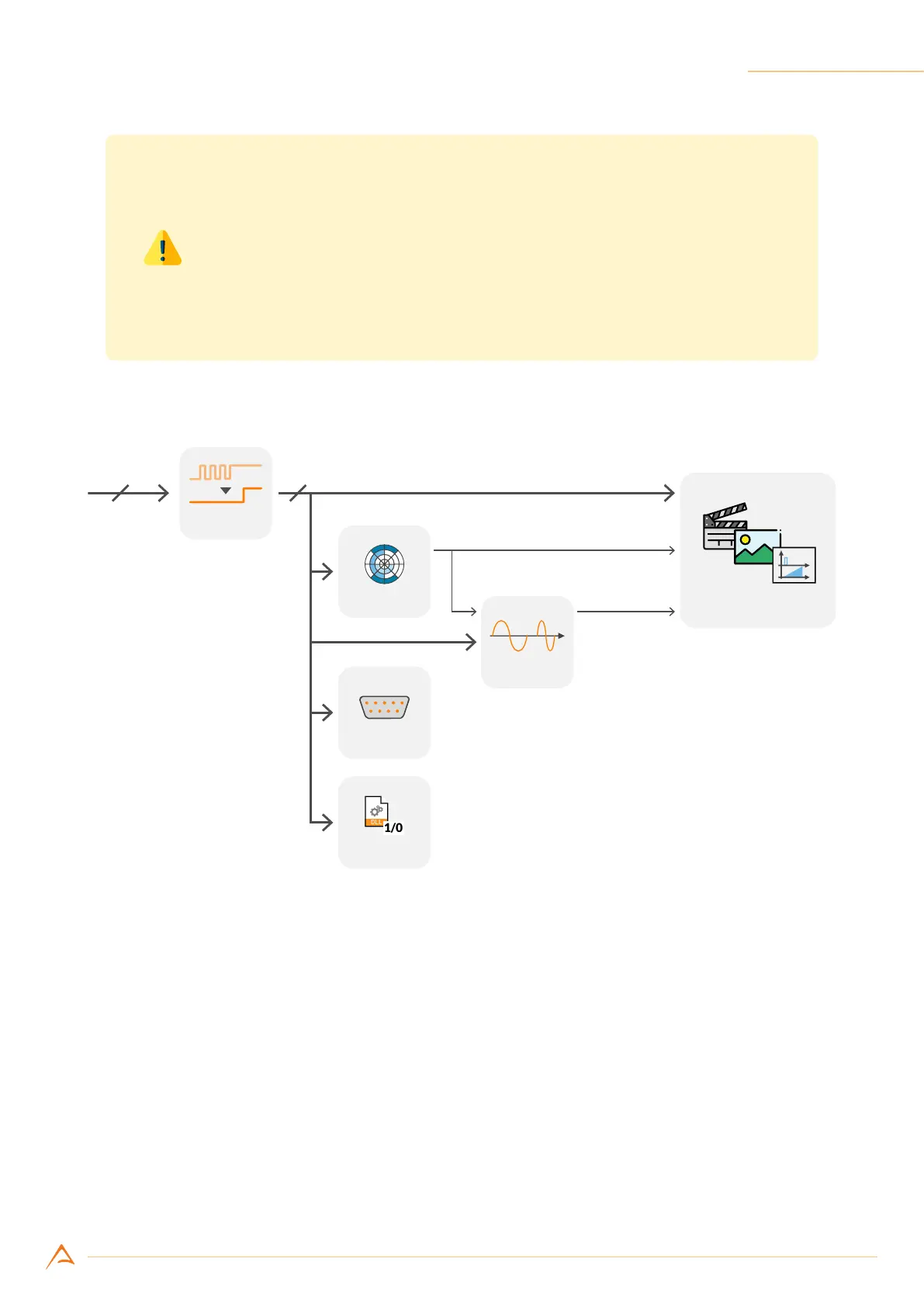
Figure 4.17: Input port internal routing
As shown in Figure 4.17, signals acquired through input ports can be routed, along with other internally
generated signals, to the internal camera processing modules; some outputs of the processing modules
can be routed to the trigger manager module, which controls camera timing and acquisition mode.
4.4.1 Encoder module
The encoder module allows interfacing the camera to an external encoder; it generates a pulse (tick)
for each encoder transition and updates a resettable counter tracking the current position. Phase and
quadrature signals (marked as A and B in Figure 4.18 and following) can be routed to any of the three
camera inputs and are fed to the encoder module after being ltered by the debouncing module (see
Section 4.3.1.1).