4. Interfacing to the world 47
Warning
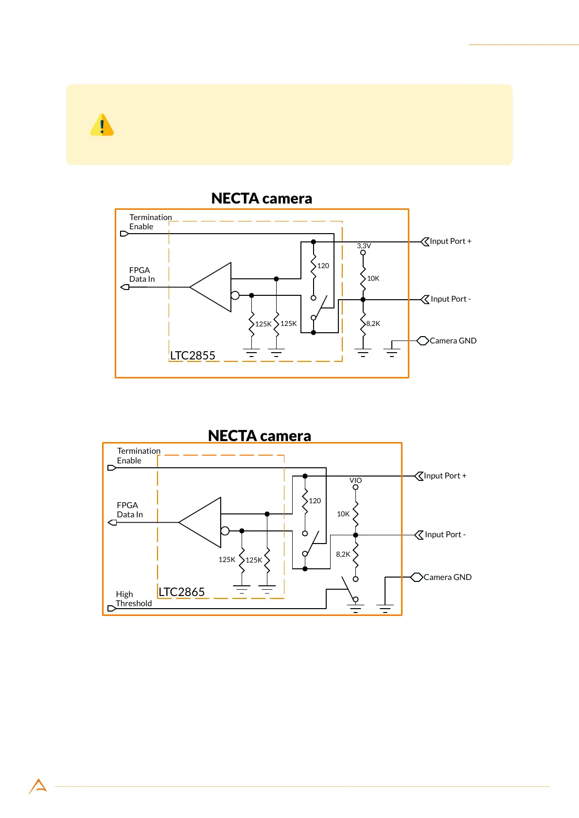
To ensure proper operation of the input circuit, the reference ground related
to input signals must be connected to the camera as well.
Figure 4.4: NECTA with 5 V tolerant input port internal structure
Figure 4.5: NECTA 24 V tolerant input port internal structure
4.3.1.1 Debouncing module
Each NECTA input line can feed a debouncing module to lter the input signal: enabling the debouncing
module allows capturing stable signals with no spurious pulses when input signal suffers from electrical
noise (e.g. signals generated by mechanical encoders or mechanical switches). The debouncing module
waits for the input signal remaining stable for at least the user-programmed time interval (orange area
in Figure 4.6); when this time is elapsed, the signal is considered valid and transferred to downstream