4. Interfacing to the world 50
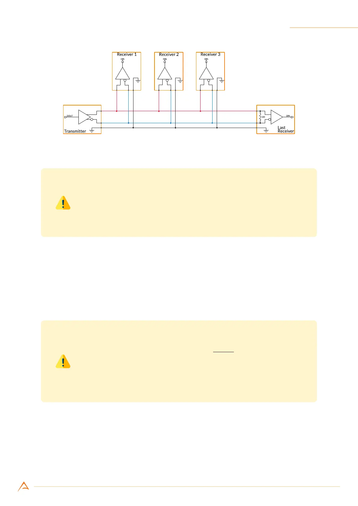
Figure 4.9: Connecting an output port to four input ports, terminating the last input port
Warning
To ensure the electrical signal integrity on the bus, you must connect only the
termination resistor (120 Ω) to the last device (on the right in the gure above).
If the last device is a NECTA camera, you can simply enable its internal termi-
nation via software (see Code 4.16).
As a general guideline, the master device (driving the bus) should be at one end of the line, the cables
connecting each device to the bus should be as short as possible and the termination should be present
(or enabled) only for the latest slave device.
4.3.1.4 RS-644
Input modules can also support RS-644 signals.
Warning
To achieve signaling compatibility, you must always keep the internal input
termination enabled, even if this is not the last device of the bus.
Moreover, although the RS-644 standard (like RS-422) allows a bus connec-
tion, we recommend using point-to-point connections only avoiding connect-
ing devices other than the RS-644 transmitter and NECTA .
4.3.1.5 LV-TTL / LV-CMOS / 12 V - 24 V
NECTA input ports natively support differential signals according to the RS-422 standard. Anyway, in-
put modules can also support single-ended LV-CMOS, LV-TTL and 12 V - 24 V signals (where available):
as shown in Figure 4.10, an internal bias network keeps the ”-” input line at a xed voltage level, that can
be congured according to the maximum voltage of the external signal. A single-ended signal connected
 Loading...