4. Interfacing to the world 53
4.3.2.1 RS-422
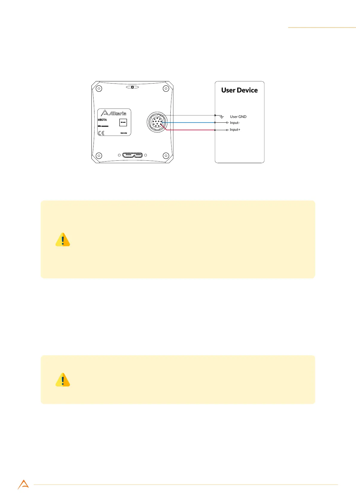
NECTA output ports natively support differential signaling according to the RS-422 standard.
Figure 4.13: Connecting output port P3 to a RS-422 input
Warning
To ensure signal integrity on the bus it is highly recommended to use the RS-
422 bus topology and keep all the bus connections to slave devices as short
as possible. The master device (the NECTA camera) must be located at one
end of the bus; a terminating resistor (120 Ω) must be connected only to the
farthest slave at the other end of the bus (see Figure 4.9).
4.3.2.2 RS-644
NECTA outputs (supporting the RS-422 standard) may also be adapted to drive devices whose inputs
follow the RS-644 standard. To make signaling compatible it is necessary to use a resistive divider, as
shown in Figure 4.14, adapting the output signal level of the camera output to the RS-644 device input
levels.
Warning
To ensure proper operation of the output circuit, the camera reference ground
must be connected to the slave device as well.
Although the RS-644 standard allows bus topology (like RS-422), we strongly recommend using point
to point connections only, avoiding connecting devices other than the NECTA camera and the RS-644
receiver.