20 Rockwell Automation Publication 440R-UM012E-EN-P - November 2018
Chapter 3 Power, Ground, and Wire
Proximity Sensor
Connections
Figure 7 - PNP Proximity Sensor Connections
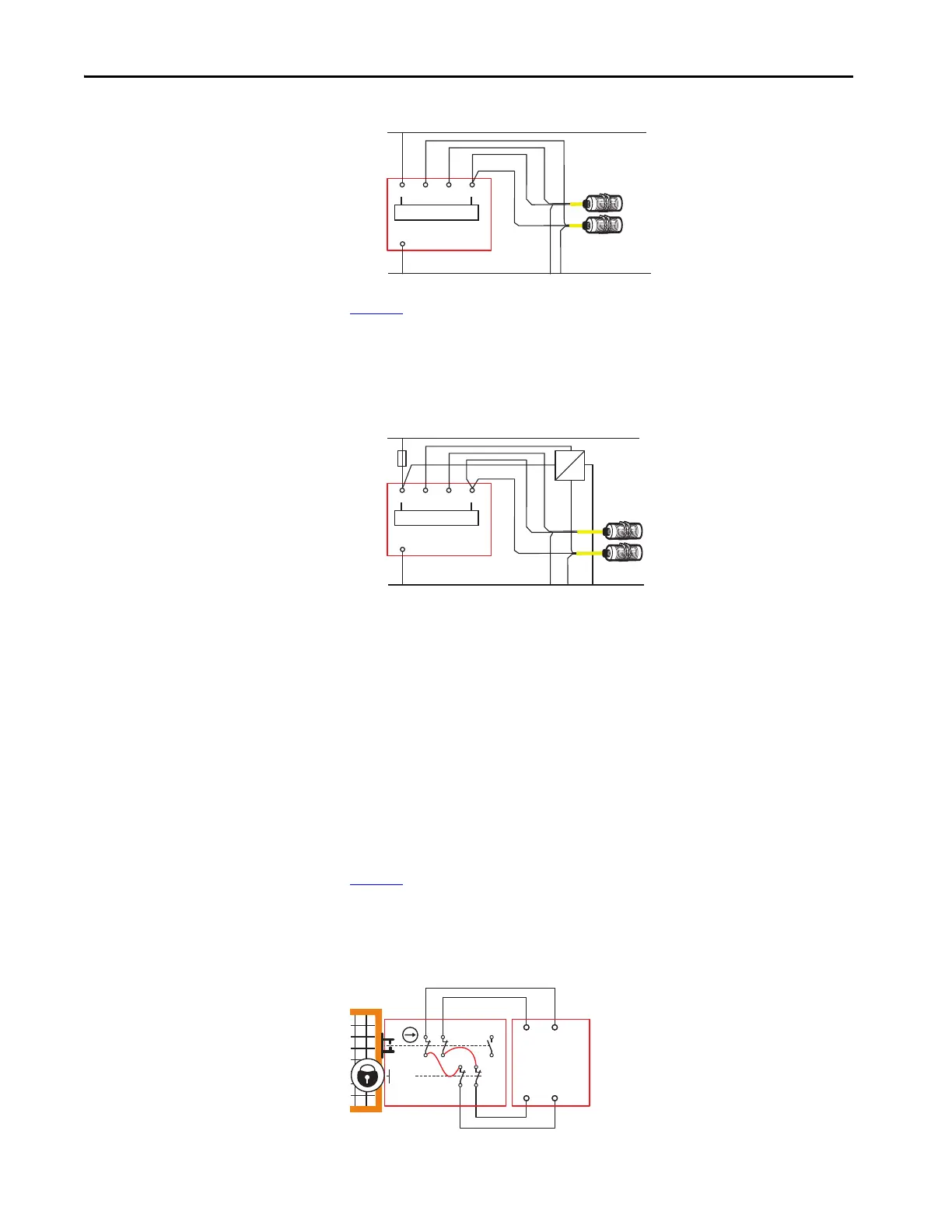
Figure 8 shows how to connect an NPN (sinking) proximity sensor. You must
provide an NPN to PNP converter. The converter should get power from AP
and have the same ground reference as the GLP safety relay. When an NPN/
PNP converter is used, a 4 A slow-blow fuse is required, and the NPN/PNP
power (+) must be connected after the fuse.
Figure 8 - PNP and NPN Proximity Sensor Connections
Guard Locking Connections
Devices with Mechanical Contacts
Guard locking devices, like the TLS3-GD2 guard locking switch, have
mechanical contact outputs, where the solenoid lock monitoring contacts are
typically connected in series with the gate monitoring contacts. Some models
of the TLS3-GD2 guard locking switch allow you to monitor the gate and
solenoid contacts separately. With its sleek, narrow body, the GLP safety relay
has only one set of safety inputs, so the series connection of the gate and
solenoid contacts are required because the gate must be both closed and locked
for production speed operations.
Figure 9
shows an example of the wiring connections from the GLP safety relay
to a TLS-GD2 guard locking switch. X14 and X24 generate test pulses that
S12 and S22 receive. The test pulses check for short circuit conditions, which,
if detected, turns off the GLP safety outputs.
Figure 9 - Example Connections to Mechanical Contacts (TLS3-GD2)
A2
GLP
+24V DC
24V Com
Power Monitoring
P12
AP
A1
P22
Brown
Brown
Black (PNP)
Black (PNP)
Blue
Blue
Proximity Sensors
+24V DC
24V Com
A2
GLP
User Supplied
NPN/PNP Converter
Power Monitoring
P12
AP
A1
P22
Fuse
4A SB
Brown
Brown
Black (NPN)
Black (PNP)
Blue
Blue
Proximity Sensors
NPN
PNP
+
-
Safety
Gate
12
22 34
11 21
33
A1
A2
42
41
52
51
S12 S22
GLT
X14
X24
TLS3-GD2

 Loading...