Rockwell Automation Publication 440R-UM012E-EN-P - November 2018 23
Power, Ground, and Wire Chapter 3
Lock Outputs
Terminals 51 and L61 perform the solenoid lock command. There are various
connection possibilities, and the GLP safety relay detects the type of
connection during configuration.
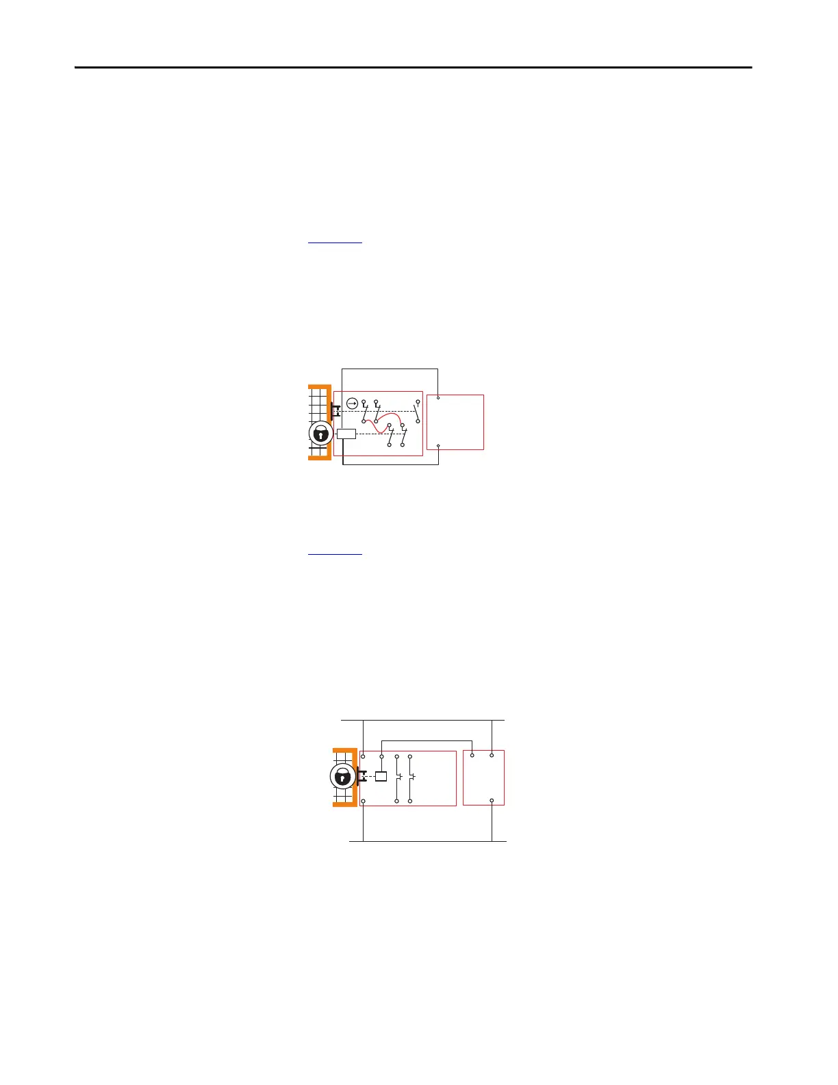
TLS3-GD2 Connections
Figure 14 shows a connection from a GLP safety relay to one TLS3-GD2
guard locking switch. Terminal 51 is connected to A1 and terminal L61 is
connected to A2.
With this arrangement, the X14/X24 L11 status indicator flashes two times
during the configuration process.
Figure 14 - Single TLS3-GD2 Connection
TLS-Z, 440G-LZ, and MAB Connections
Figure 15 shows one connection from a GLP safety relay to one TLS-Z guard
locking switch, 440G-LZ guard locking switch, and Bulletin 442G
Multifunction Access Box (MAB). Terminal 51 is connected to A1 and
terminal L61 is left open. The GLP safety relay and guard locking switch must
have a common reference.
With this arrangement, the X14/X24 L11 status indicator flashes one time
during the configuration process.
Figure 15 - Single TLS-Z, 440G-LZ, or MAB Connection
Safety
Gate
12
22
34
11
21
33
A1
A2
42
41
52
51
L61
GLP
51
TLS3-GD2
GLP
51
A1
A2
+24V DC
TLS-Z,
440G-LZ
or MAB
24V DC Com

 Loading...