Rockwell Automation Publication 440R-UM012E-EN-P - November 2018 31
Chapter 5
Diagnostic Status Indicators and
Troubleshooting
The GLP safety relay has five status indicators to provide operating status and
diagnostic information.
Status Indicators During
Power-up
During power-up, the status indicators turn ON and OFF during their self-
check process. The self-check takes about 5 seconds for Status Only Logic and
10 seconds for all other Logic Settings.
Status Indicators During
Normal Operation
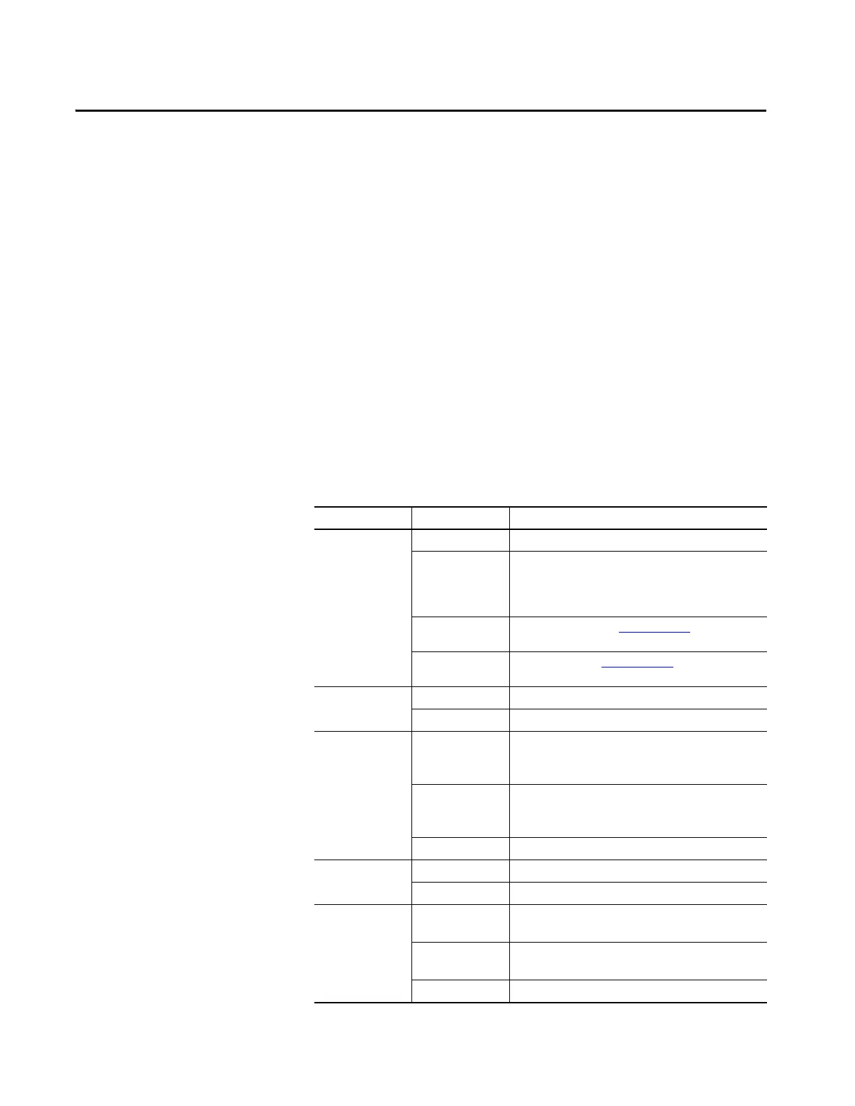
Table 6 - Normal Operation Status Indicators
Status Indicator State Description
PWR/FAULT Solid Green Normal operation.
Blinking Green On power-up, the gate appears open.
Close the gate or verify 24V DC at terminals S12 and S22.
If your guard locking devices use mechanical inputs, start
configuration from 9.
Blinking Red Non-recoverable fault. See Table 7 on page 32
.
Correct fault and cycle power.
Green with Blinking
Red
Recoverable fault. See Table 7 on page 32.
Correct fault and press reset.
IN 1 ON Input circuits at S12 and S22 are closed.
OFF Input circuits at S12 and S22 are open.
51/L61 ON Gate is locked with Logic Setting 1…4.
Output is active with Logic Setting 5…8.
51 and L61 are ON with Status Only.
OFF Gate is unlocked with Logic Setting 1…4.
Output is inactive with Logic Setting 5…8.
51 and L61 are OFF with Status Only.
Blinking Timing cycle has started.
LOGIC IN ON Logic IN signal at L12 is active.
OFF Logic IN signal at L12 is OFF.
X14/X24 L11 ON L11 is active and X14/X24 are ON.
L11 is active and X14/X24/Y32 are ON with Status Only.
OFF L11 is OFF and X14/X24 are OFF.
L11 is OFF and X14/X24/Y32 are OFF with Status Only.
Blinking Waiting for reset signal or timing cycle has started.

 Loading...