Rockwell Automation Publication 440R-UM012E-EN-P - November 2018 33
Chapter 6
Pulse Testing Functions
Introduction to Pulse Testing
The test pulses are used by the GLP safety relay to detect three short-circuit
conditions:
• Between the input terminals and +24V
• Between the input terminals and 24V common
• Between the two input terminals.
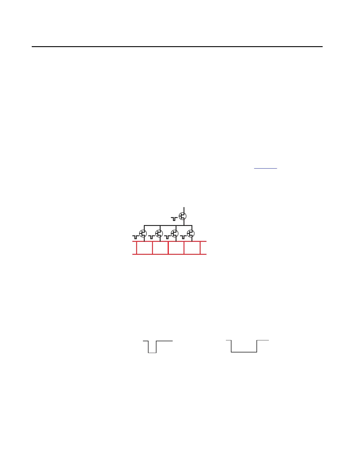
The outputs have built in redundancy, as shown in Figure 24
. A main transistor
supplies power to individual transistors for each output terminal. This
arrangement provides the redundant output to achieve the Cat. 3 and SIL 2
safety rating.
Figure 24 - Output Transistor Arrangement
The GLP safety relay continuously tests all transistors. When the main
transistor is tested, a 50-µs pulse appears on all outputs simultaneously. When
the individual transistors are tested, the test pulse only appears on their
respective terminals.
The main transistor test is predominately 50 µs but can be as long as 350 µs.
The pulse width on X14, X24, 51, and L61 is between 200…850 µs.
Figure 25 - Output Pulse Test Width
Main Transistor
Individual Transistors
24V
00
0V
50…350 µs 200…850 µs
24V
0V
Main Transistor X14, X24, 51, and L61

 Loading...