22 Rockwell Automation Publication 440R-UM012E-EN-P - November 2018
Chapter 3 Power, Ground, and Wire
Lock and Reset Request
Input
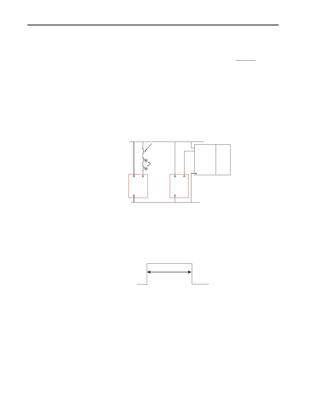
The Lock and Reset Input can be connected to the 24V supply through a
momentary, normally open push button switch or to a 24V sourcing output of
a PLC, where the PLC turns the request ON or OFF. Some examples of
RockwellAutomation PLC output modules are shown in Figure 12
.
In some safety system applications, the reset signal also serves as a monitoring
function. For example, when the safety outputs are driving safety contactors,
the normally closed contacts of the safety contactors should be connected in
series with lock and reset circuit.
If an unlock request is made, and the machine speed has not dropped below the
SLS1 setting, pressing the Reset button cancels the unlock request.
The lock and reset request is connected to Terminal S44.
Figure 12 - Lock Request Wiring
Lock and Unlock Signals
The GLP safety relay is designed to ignore incidental actuations or stuck
conditions on the Lock and Unlock inputs. The lock and unlock signals must
be actuated for a duration between 0.25…3 seconds. The GLP safety relay
ignores signal durations that are too short or too long.
Figure 13 - Required Signal Duration
+24V DC
24V DC Com
+
1
2
3
Momentary
Normally-Open
Push Button
PLC Output
1756-OB16
1769-OB8
1746-OB4
1734-OB2
1793-OB4
PLC
Processor
GLP
S44
A1
A2
GLP
S44
A1
A2
Contactor
Monitoring
+24V DC
250…3000ms
24V DC Com

 Loading...