46 Rockwell Automation Publication 440R-UM012E-EN-P - November 2018
Chapter 9 Example Operational Sequence Diagrams
SLS Example
This example shows a typical application where the GLP safety relay is used in
a Stop Category 1 application.
Example Schematic
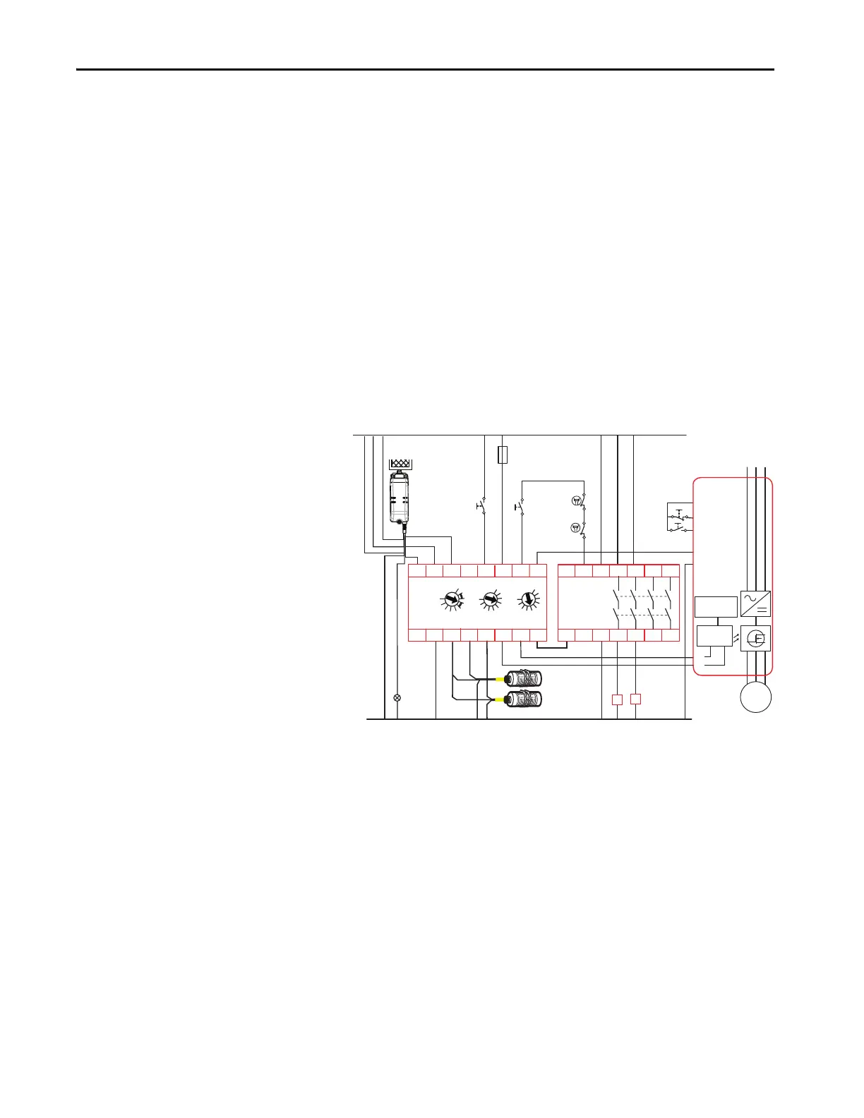
In this example, we have a GLP safety relay that controls a 440G-LZ Power to
Release guard locking interlock, drives a PowerFlex 525 AC drive, and is
connected to an EM expansion safety relay.
The Y32 output is directly connected to terminal 5 of the PF525 drive, which
is configured to be set to a Preset Frequency. When Y32 goes HI, the PF525
drive immediately sets the motor to run at the predetermined speed.
In this example, the 440G-LZ guard locking switch can easily replace by the
TLS-ZR guard locking switch.
Figure 40 - Schematic for Safely Limited Speed Example
+24V DC
24V DC Com
Gate
Unlock
Request
Reset &
Gate Lock
Request
Brown
Red
Yellow
White
Blue
Grey
Green
Pink
LightLatch
440G-LZS21SPRA
Gate
Unlocked
K1
Fuse
4 A SB
K2
Gate control
power supply
Gate control
circuit
M
4 Gnd
S1
S2
1 Stop
L1 L2 L3
PowerFlex
525
2 Start
5 Preset Freq
11 +24V DC
RTS
UWV
A1
L11
X32
L12 14 34 4424
13 33 4323
A2
EM
440R-EM4R2
Brown
Black
Black
Blue
Blue
Proximity
Sensors
LOGIC SLS1
0
1
2
3
4
5
6
7
8
9
0
1
2
3
4
5
6
7
8
9
SLS2/TIME
0
1
2
3
4
5
6
7
8
9
GLP
440R-GL2S2P
A2
S12 S22
L11
L12
L6151
P12 P22
A1
X14 X24
S44S54
AP
Y32
K1
K2

 Loading...