Rockwell Automation Publication 440R-UM012E-EN-P - November 2018 25
Power, Ground, and Wire Chapter 3
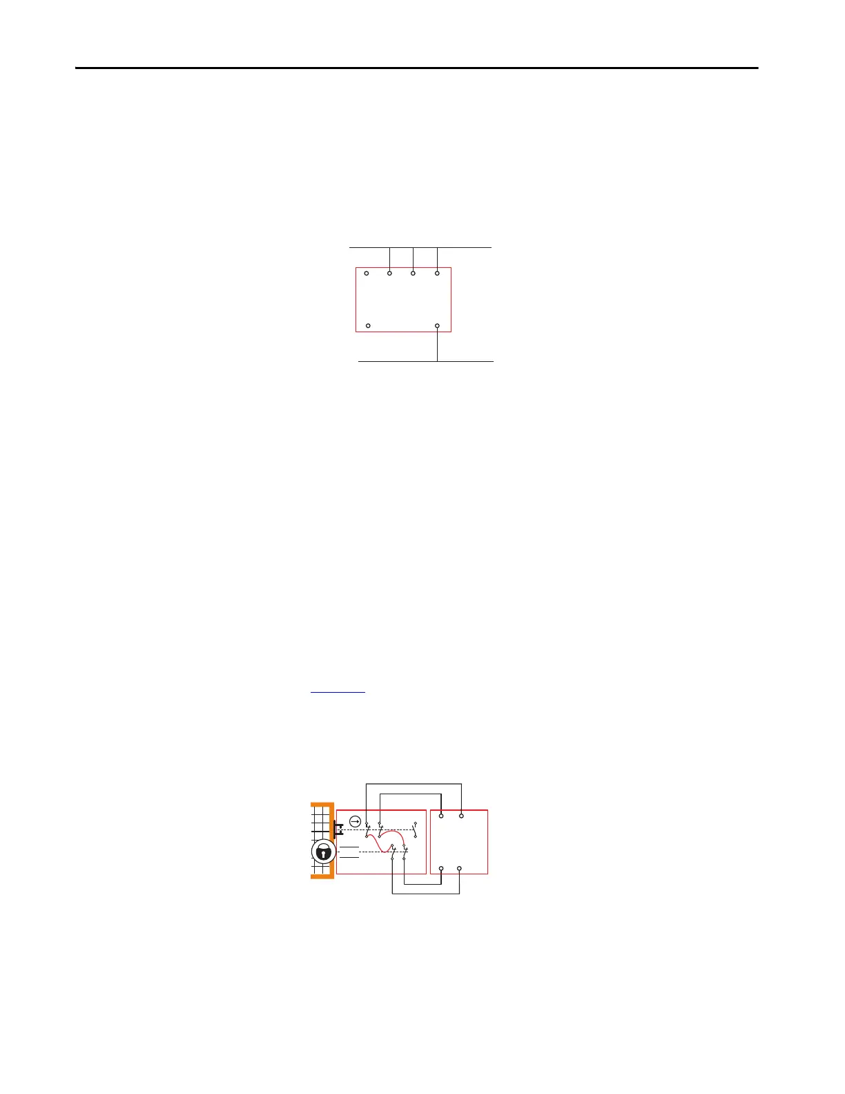
No Guard Locking
If no guard locking is required for Stop Cat 1 or SLS functions, then 51 and
L61 can be left open. The safety inputs S12 and S22 must be connected to 24V
DC. With this arrangement, the X14/X24 L11 status indicator blinks one
time during the configuration process.
Figure 17 - No Guard Locking Connections
Safety Outputs
Terminal X14 and X24 can be configured as pulse test outputs or safety
outputs. Start the configuration process from 9 to configure X14 and X24 as
pulse test outputs. Start the configuration process from 0 to configure X14 and
X24 as safety outputs.
When configured as pulse test outputs, the GLP safety relay continuously
provides 24V DC combined with short test-pulse signals on terminals X14 and
X24. This configuration is used in applications with guard locking devices that
have mechanical contacts. The purpose of the pulse testing is to test for the
following short-circuit conditions:
• Between X14 and X24
• From X14 or X24 to 24V DC
• From X14 to X24 to 24V common
Figure 18
shows an example wiring connection of the pulse testing outputs
(X14 and X24) connected to a TLS3-GD2 guard locking switch. The output
signals are fed through the mechanical contacts and back to the safety inputs
(S12 and S22) of the GLP safety relay.
Figure 18 - Pulse Test Output Connections
When configured as safety outputs, terminals X14 and X24 are safety outputs.
The safety outputs are only turned ON when safe conditions are met. When
configured as safety outputs, these terminals test for short circuits when they
are turned ON. The safety outputs are commonly referred to as OSSD
outputs.
GLP
L61
51 A1
A2
+24V DC
24V DC Com
S22S12
Safety
Gate
12
22 34
11 21
33
A1
A2
42
41
52
51
X14
GLP
S12
TLS3-GD2
S22
X24

 Loading...