18 Rockwell Automation Publication 440R-UM012E-EN-P - November 2018
Chapter 3 Power, Ground, and Wire
Terminal Assignments
Some terminals are designed to have one specific function. Some terminals can
perform multiple functions; these terminals must be configured during a
power-up routine.
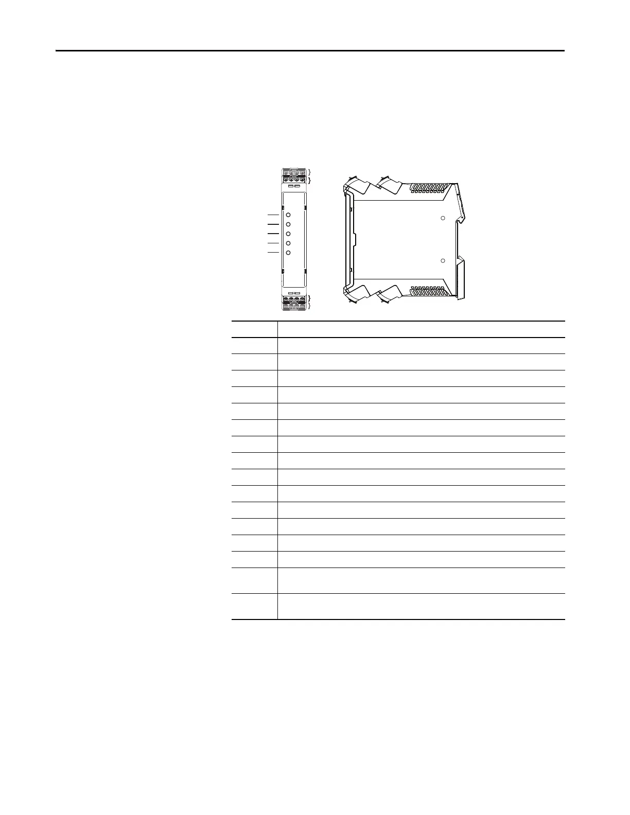
Figure 5 - Terminal Identification
Terminal Function
A1 +24V Supply (+10%, -15%)
A2 24V Common
AP Power Supply for Proximity Sensors
P12 Proximity Sensor Input Channel 1
P22 Proximity Sensor Input Channel 2
S12 Safety Input for Channel 1
S22 Safety Input for Channel 2
S44 Reset and Lock Request Input
S54 Guard Locking Unlock Request Input
Y32 Auxiliary Non-safety Output
L11 Single Wire Safety Output
L12 Single Wire Safety Input
51 Guard Locking Solenoid Output Channel 1 (High Side)
L61 Guard Locking Solenoid Output Channel 2 (Low Side, High Side, or Logic Link Output)
X14 Configured as either a pulse test output that is expected at one of the safety input channels or an
OSSD safety output
X24 Configured as either a pulse test output that is expected at one of the safety input channels or an
OSSD safety output
S12 S22 AP S54
A1 A2 P12 P22
X2
X1
X1
X2
X3
X4
X3 X4
PWR/Fault
IN1
51/L61
Logic IN
X14/X24 L11
L12 L11 Y32 S44
X14 X24 51 L61

 Loading...