52 Rockwell Automation Publication 440R-UM012E-EN-P - November 2018
Chapter 9 Example Operational Sequence Diagrams
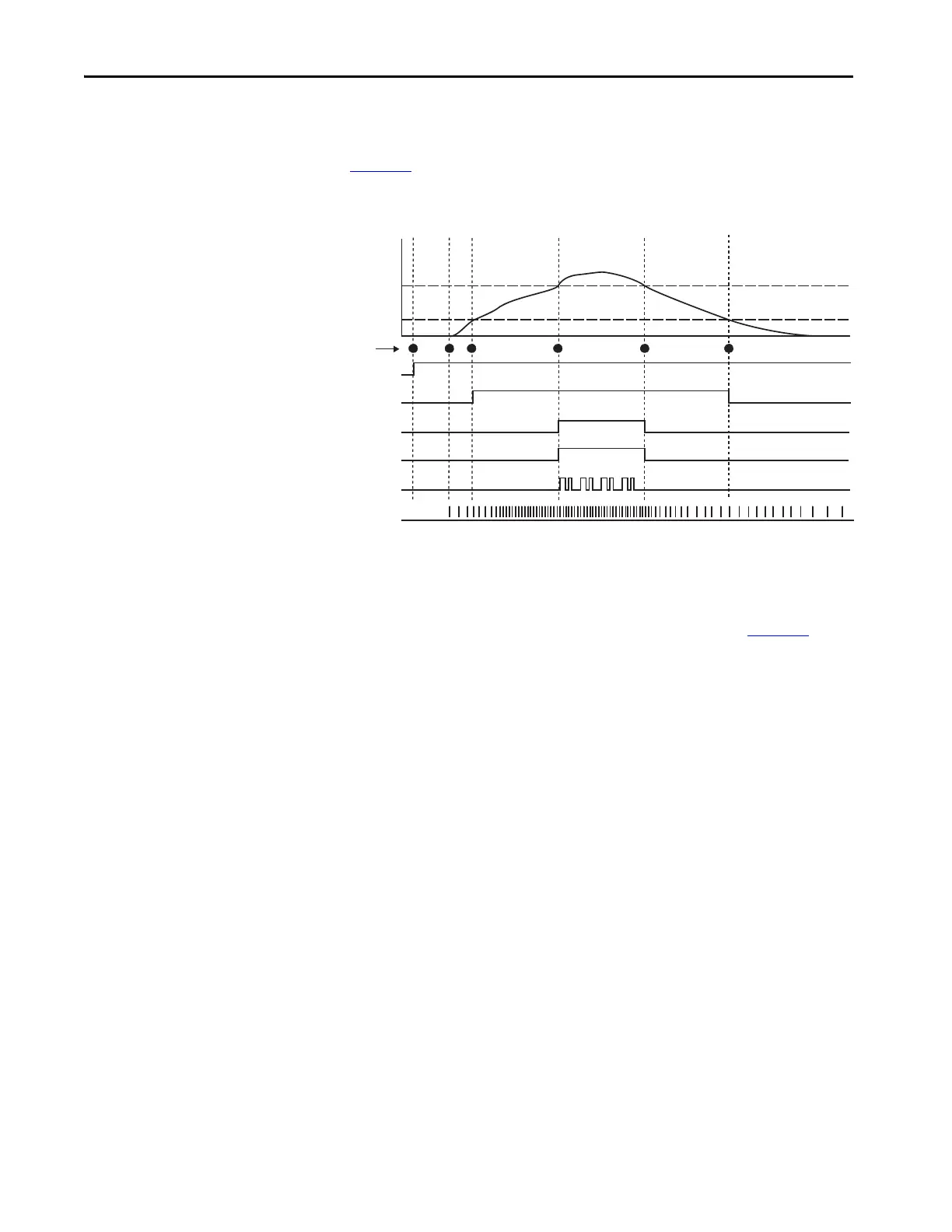
Sequence Diagram
Figure 45 the sequence of operations. This diagram assumes that all
components are operating properly and no faults are present.
Figure 45 - Operational Sequence for Status Only Example
Sequence Steps
The following steps describe each of the highlighted points in Figure 45.
1. 24V DC power is applied to the safety system. The safety devices
perform their internal tests.
2. Because the proximity sensors do not detect any motion, the GLP safety
relay maintains all of its outputs in the OFF state. The proximity sensors
detect and increase in the speed of the machine.
3. When the speed increases past the SLS1 setting, the 51/L61 outputs
turn ON.
4. When the speed increases past the SLS2 setting, the GLP safety relay
turns on the remaining outputs (X14/X24/L11 and Y32).
5. When the speed decreases below SLS2, the GLP safety relay turns
X14/X24/L11 and Y32 OFF.
6. When the speed decreases below SLS2, the GLP safety relay turns
51/L61 OFF.
Power
L11
Y32
On
O
24V
0V
24V
0V
24V
0V
X14/X24
24V
0V
51/L61
24V
0V
Proximity Sensors
SLS1 Speed
SLS2 Speed
1 2 3 5 64
Sequence Steps

 Loading...