28 Rockwell Automation Publication 440R-UM012E-EN-P - November 2018
Chapter 4 Configuration
SLS1 Switch Setting
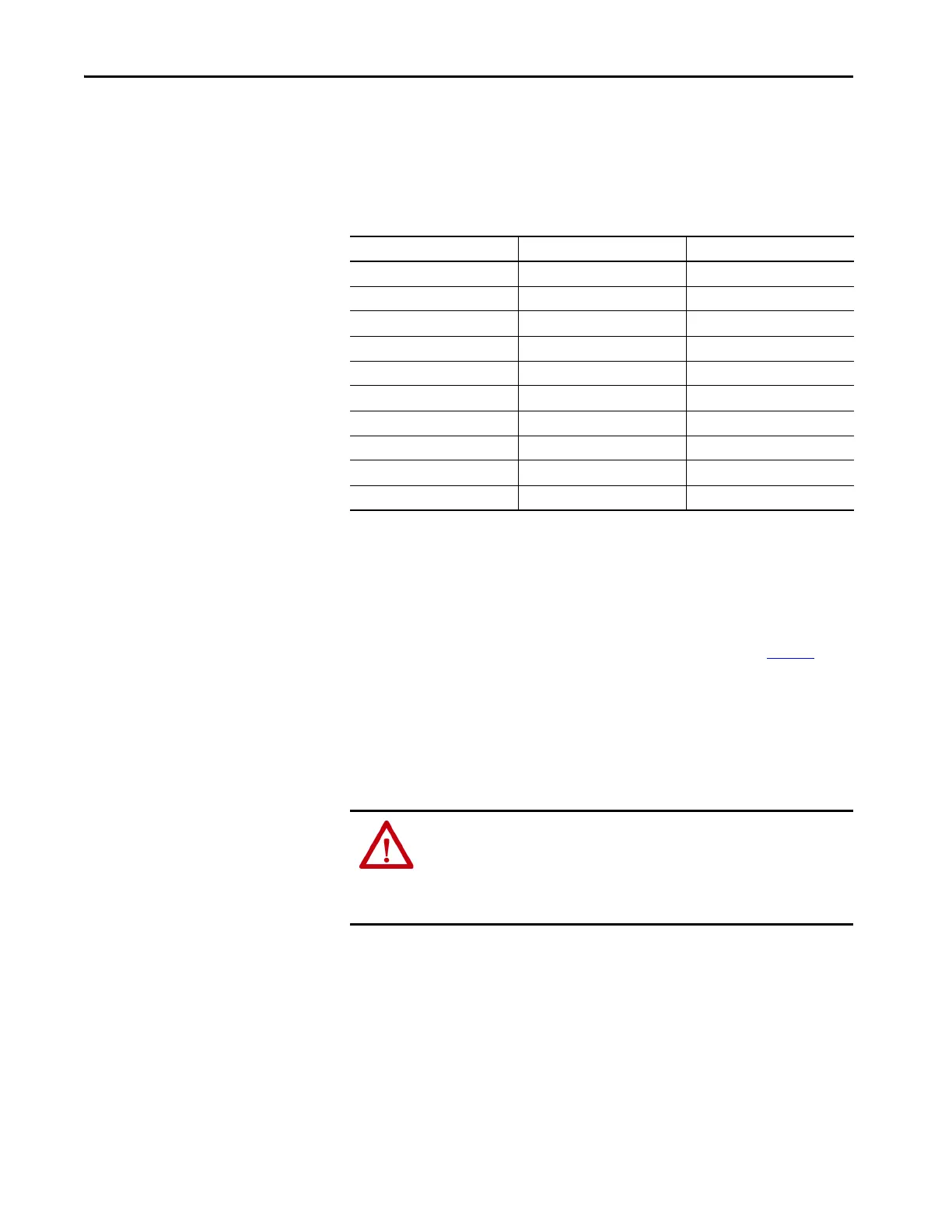
SLS1 is a 10-position switch that determines the safe limited slow speed, as
detected by the proximity sensors, or the Safe Stop Threshold (Speed1).
Switch SLS1 applies to all eight logic settings.
Table 3 - SLS1 Settings
SLS2/Time Switch Setting
SLS2/Time is a 10-position switch.
When the Logic Switch is set to positions 1…4, SLS2/Time determines the
safe limited fast speed, as detected by the proximity sensors. The safety outputs
turn OFF when the speed exceeds the frequency that is shown in Table 4
.
When set to 0, the GLP safety relay does not test for maximum speed.
When the Logic Switch is set to positions 5…8, SLS2/Time determines the
time delay from 10…100% of the Range set by the Logic position.
Time Delay = (10%...100% x Time Range) + Frequency Measuring Time
SLS1 Switch Setting Maximum SLOW Speed Frequency Measuring Time
0 0.5 Hz 10100 ms
1 1 Hz 5050 ms
2 2 Hz 2550 ms
3 3 Hz 1750 ms
4 4 Hz 1350 ms
5 5 Hz 1100 ms
6 6 Hz 950 ms
7 7 Hz 800 ms
8 8 Hz 700 ms
9 10 Hz 600 ms
ATTENTION: When the frequency of the objects that pass in front of the
proximity sensors exceeds the sensors capability, the proximity sensors give
a false signal. To help protect against this potential unsafe condition, you
must set SLS2/Time to a value that does not exceed the maximum frequency
rating of the proximity sensors.

 Loading...