Rockwell Automation Publication 440R-UM012E-EN-P - November 2018 27
Chapter 4
Configuration
The GLP safety relay has three multi-position switches on its front panel.
These switches set the configuration of the GLP safety relay.
Logic Switch Settings
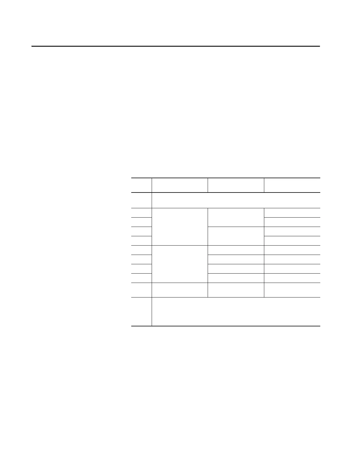
The Logic switch determines the operating function of the GLP safety relay
and is used to set the configuration.
Table 2 - Logic Switch Setting
Switch 1
Setting
Lock/ Unlock Door Control
Out Configuration
Application Logic in
0 Configuration
1…8 Program mode X14 and X24 configured as OSSD Outputs
1Guard Locking
Power to Release
Cat 1 Stop Logic in OFF
2 Logic in AND IN1
3 Safely Limited Speed Logic in OFF
4 Logic in AND IN1
5Guard Locking
Power to Release
Delayed Unlock
Automatic Reset
(configuration from “0” only)
On-delay 1…10 s Logic in OFF
6 On-delay 3…30 s Logic in OFF
7 On-delay 30…300 s Logic in OFF
8 (1) On-delay 300…3000 s Logic in OFF
8 (2) Speed1 and Max Speed status
only (Configuration from “9”)
Status only Logic in OFF
9 Configuration
1…4 Program mode X14 and X24 are configured as Pulse Tested Outputs for the S12 and S22 Inputs
5…7 Program mode is not allowed
8 for speed status only with X14 and X24 as OSSD Outputs.

 Loading...