24 Rockwell Automation Publication 440R-UM012E-EN-P - November 2018
Chapter 3 Power, Ground, and Wire
Multiple Guard Locking Devices and Power to Lock
When multiple guard locking devices must be connected to one GLP safety
relay, an interposing relay or interposing relays may be required; the connection
depends on the lock signal/coil characteristics. The solenoids would be driven
by the contacts of the interposing relays.
The interposing relays must also be used to for those applications where Power
to Lock guard locking is required.
Some devices, like the TLS3-GD2 guard locking switch, 440G guard locking
switch, and Bulletin 100S safety contactors (with electronic coils) have built-in
diodes, so an external diode is not required.
With CR1 connected between 51 and L61, the X14/X24 L11 status indicator
flashes two times during the configuration process. With two relays (CR1
connected between 51 and ground and CR2 connected between L61 and
ground), the X14/X24 L11 status indicator blinks one time during the
configuration process.
The 700-HPSXZ24 relay can be connected between 51 and L61. The 100S
contactors cannot be connected between 51 and L61. The 100S contactors
must be connected between 51 and 0V or L61 and 0V.
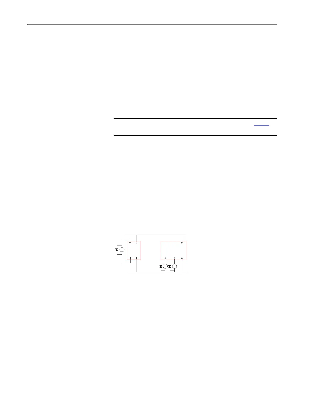
Figure 16 - Interposing Relay Connections
TIP The lock signal of TLS-Z and 440G-LZ guard locking switches draw under
4 mA, which allows you to connect the lock signal of multiple switches in
parallel.
IMPORTANT The GLP safety relay requires a suppression diode, as shown in Figure 16
, for
proper operation.
GLP
L61
51
A1
A2
+24V DC
24V DC Com
CR1
GLP
L6151
A1
A2
CR1 CR2

 Loading...