Rockwell Automation Publication 440R-UM012E-EN-P - November 2018 47
Example Operational Sequence Diagrams Chapter 9
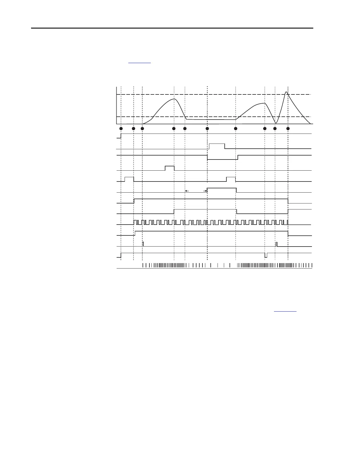
Sequence Diagram
Figure 41 shows the sequence of operations. This diagram assumes that all
components are operating properly and no faults are present.
Figure 41 - Operational Sequence for Safely Limited Speed Example
Sequence Steps
The following steps describe each of the highlighted points in Figure 41.
1. 24V DC power is applied to the safety system.
Because the gate is closed, the 440G guard locking switch has locked the
gate. With the gate closed and locked, the GLP safety relay is ready for
reset.
2. You press and release the Reset button (hold for 250…3000 ms).
Terminals X14 and X24 go HI, which enables the Safe Torque Off
function of the PowerFlex 525 drive.
The single wire safety output at L11 starts oscillating. The EM
expansion relay energizes and turns on contactors K1 and K2.
Power
Operator Location
Gate Status (S12, S22)
Unlock Request
Reset & Lock Request
L11
Y32
250ms 250ms
250ms
Overspeed
On
O
Locked
Unlocked
24V
0V
24V
0V
24V
0V
Closed
Open
24V
0V
24V
0V
24V
0V
X14 and X24
24V
0V
Lock Signal (51/ L61)
Power to Release
24V
0V
EM Ouputs
Start Button
Stop Button
Safely Limited Speed
(SLS1)
Max Safe Speed
(SLS2)
Operator
In Cell
In Cell
Out of Cell
Gate is unlocked
24V
0V
Proximity Sensors
Frequency
Measurement
Time
Unlock Lock
1 2 3 4 5 6 7 8 9 10

 Loading...