Rockwell Automation Publication 440R-UM012E-EN-P - November 2018 43
Chapter 9
Example Operational Sequence Diagrams
This chapter provides operational sequence diagrams of typical GLP
applications. The purpose of provide you with a better insight of some of the
performance characteristics of the GLP safety relay.
Stop Cat 1 Example
This example shows a typical application where the GLP safety relay is used in
a Stop Category 1 application.
Example Schematic
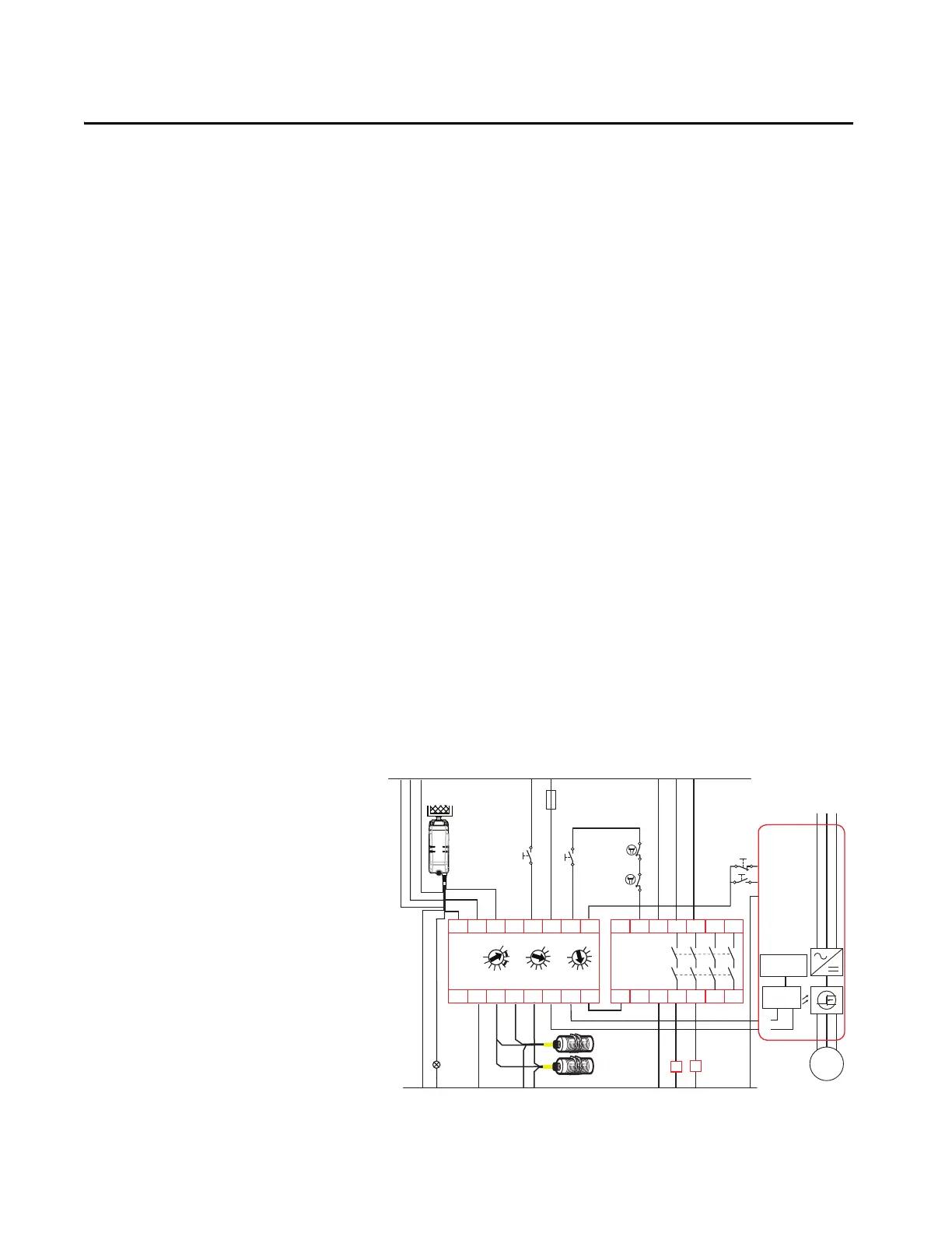
In this example, we have a GLP safety relay that controls a 440G-LZ Power to
Release guard locking interlock, drives a PowerFlex® 525 AC drive, and is
connected to an EM expansion safety relay.
The Y32 output is directly connected to the Start and Stop terminals of the
PF525 drive. When Y32 goes HI, the PF525 drive can be started. When Y32
goes LO, the drive executes its pre-configured stop function.
In this example, the 440G-LZ guard locking switch can easily replace by the
TLS-ZR guard locking switch.
Figure 38 - Schematic for Stop Cat 1 Example
+24V DC
24V DC Com
Gate
Unlock
Request
Reset &
Gate Lock
Request
Brown
Red
Yellow
White
Blue
Grey
Green
Pink
LightLatch
440G-LZS21SPRA
Gate
Unlocked
K1
Fuse
4 A SB
K2
Gate control
power supply
Gate control
circuit
M
4 Gnd
S1
S2
1 Stop
L1 L2 L3
PowerFlex
525
2 Start
RTS
UWV
A1
L11
X32
L12 14 34 4424
13 33 4323
A2
EM
440R-EM4R2
Brown
Black
Black
Blue
Blue
Proximity
Sensors
LOGIC SLS1
0
1
2
3
4
5
6
7
8
9
0
1
2
3
4
5
6
7
8
9
SLS2/TIME
0
1
2
3
4
5
6
7
8
9
GLP
440R-GL2S2P
A2
S12 S22
L11
L12
L6151
P12 P22
A1
X14 X24
S44S54
AP
Y32
K1
K2

 Loading...