Rockwell Automation Publication 440R-UM012E-EN-P - November 2018 9
Chapter 1
Overview
Hardware Features
The Guard Locking Proximity (GLP) inputs special-purpose safety relay is
designed to use proximity sensors to detect the safe speed of a machine. The
GLP safety relay issues lock or unlock commands to a guard locking interlock
based on the speed of the signals that are received from the proximity sensors.
The GLP safety relay has three rotary switches that are used to set its
configuration. A logic switch sets the functionality. Two other switches set
speed limits and time delay: Switch SLS1 sets the safe limited slow speed.
Switch SLS2 set the safe maximum speed limit or a percentage of the timing
range.
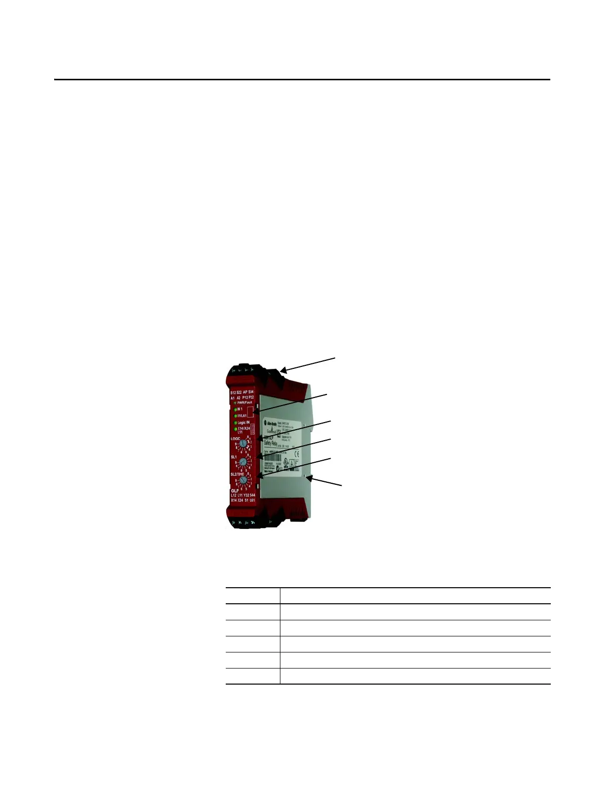
Figure 1 - GLP Safety Relay
Five status indicators provide status and diagnostic information.
Table 1 - Status Indicator Information
The GLP safety relay has four removable terminal blocks; two on the top and
two on the bottom.
Indicator Description
PWR/Fault Indicates that power is applied or a fault condition
IN1 Indicates that the safety gate is closed, input valid.
51/L61 Indicates that power is applied to unlock the guard locking interlock.
Logic IN Indicates the presence of the Single Wire Safety input signal.
X14/X24 L11 Indicates that the safety outputs are ON.
Removable terminal blocks
Five status indicators for status and diagnostics
SLS1 sets the safe limited slow speed
Logic switch sets functionality
SLS2/Time sets the maximum safe speed
or percentage of time delay
Optical communication bus

 Loading...