30 Rockwell Automation Publication 440R-UM012E-EN-P - November 2018
Chapter 4 Configuration
2. Apply power.
The PWR/Fault status indicator flashes red continuously. The prior
configuration in the EEPROM is erased and the device now prepared
for a new configuration.
3. Adjust the Logic, SLS1, and SLS2/Time switches.
After 500 ms, the new configuration parameters are acknowledged.
Then, after 300 ms, the new parameter is stored in the EEPROM, the
power status indicator is solid green.
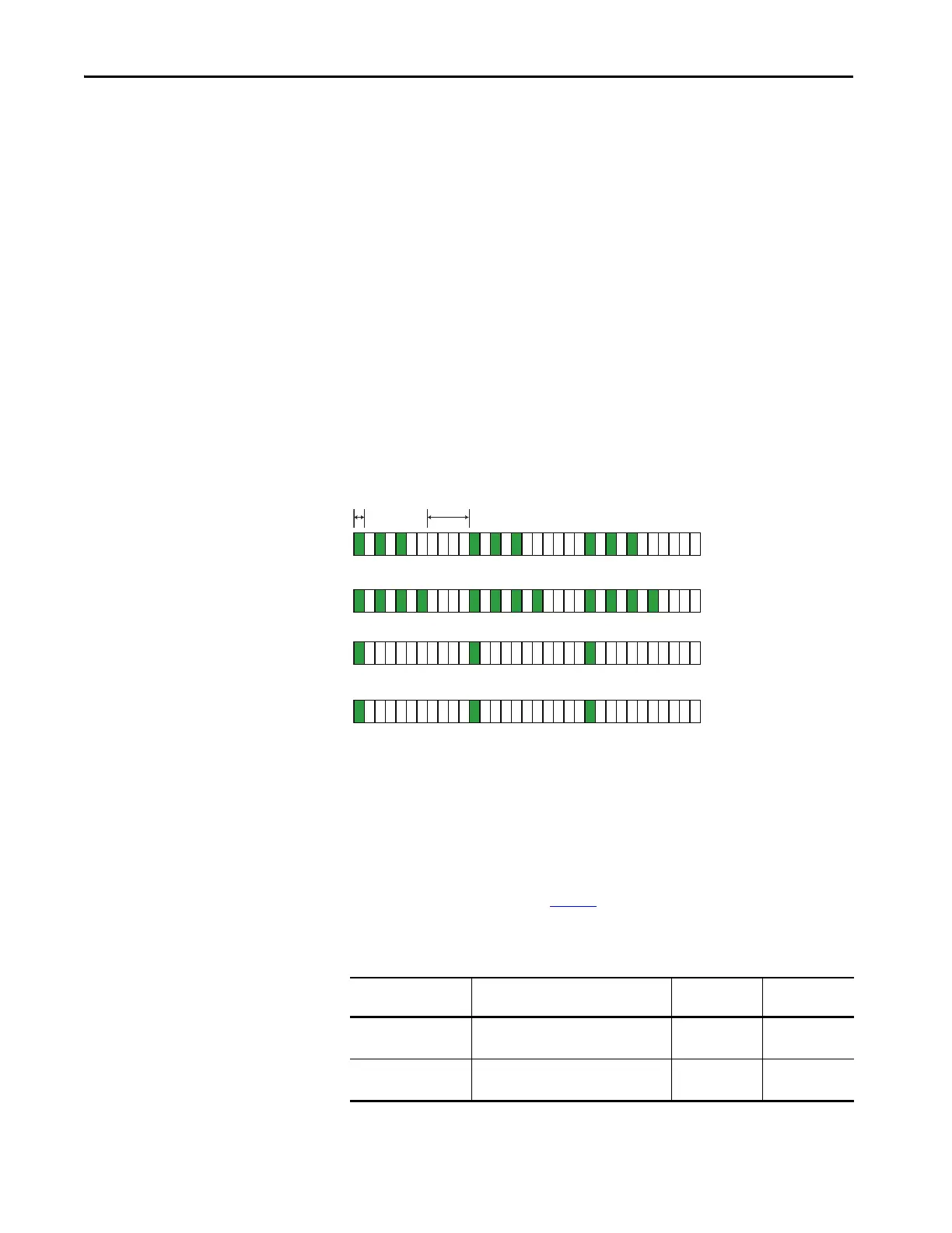
4. Verify the settings by counting the blink rates of the status indicators.
The status indicators flash for 0.5 seconds to indicate the switch setting.
The number of flashes is equal to the switch setting. The blinking
repeats after a two-second pause.
Figure 23 - Example of the Status Indicators Flashing during Configuration Mode
5. Cycle the power to store the settings.
After power-up, the current switch settings are compared to the values in
the EEPROM, and the input and output circuits are checked. Upon
successful completion of the internal checks, the GLP safety relay is
ready for operation.
The X14/X24 L11 status indicator indicates the type of connection that is
made to terminals 51 and L61. Ta ble 5
shows the conditions for the X14/X24
L11 status indicator blink rates.
Table 5 - X14/X24/L11 Status Indicator
TIP You can change (or readjust) the switch settings during Step 3 and
4. The power status indicator momentarily flashes red again.
X14/X24/L11 Status
Indicator Blinks
Guard Locking Switch 51 L61
One time OSSD Guard Locking Switch
(for example, TLS-ZR or 440G-LZ)
High side High side
Two times Standard Guard Locking Switch
(for example, TLS3-GD2)
High side Low side
IN1 - Indicates that the LOGIC switch is set to 3
51/L61 - Indicates that the SLS1 switch is set to 4
Logic IN - Indicates that the SLS2/time switch is set to 1
X14/X24 L11 - Indicates the solenoid connection to guard locking switch with OSSD outputs

 Loading...